
Water pump reset structure for cooling fan

A technology of reset structure and cooling fan, applied in the field of water pump reset structure, can solve the problems of water pump reset mechanism or water tank damage, reduction of the total weight of the water tank, corrosion of elastic components, etc., to achieve overall cost reduction, simplification of rocker principle, and easy installation and disassembly. Effect

Active Publication Date: 2017-03-22
SHUNDE KINGTEC APPLIANCES CO LTD
View PDF8 Cites 0 Cited by
  • Summary
  • Abstract
  • Description
  • Claims
  • Application Information

AI Technical Summary

Problems solved by technology

[0004] The published Chinese patent 201210224213.3 has provided a better structural method to solve the problem that the water pump sinks into the bottom of the water tank or is lifted when the water tank is pushed in or pulled out, but the reset structure of the patent structure adopts elastic elements ( Including coil spring, torsion spring or shrapnel), the elastic element of this material is made of iron casting. When the elastic element is exposed to the water vapor generated by the cooling fan and the moisture in the water tank for a long time, it is easy to rust the elastic element and cause the elasticity to decay. It is easy to cause the suspension of the water pump bracket to be lower than the height of the water tank, so that the water tank will collide with the water pump when it is pushed in next time, causing damage to the reset mechanism of the water pump or the water tank. It is easy to cause the force of the elastic element of the water pump reset mechanism to be greater than the weight of the water tank, so that the water tank is pushed out of the water tank installation cavity during use

Method used


Image

  • Water pump reset structure for cooling fan
  • Water pump reset structure for cooling fan
  • Water pump reset structure for cooling fan

Examples


Embodiment Construction

[0024] Below in conjunction with accompanying drawing and embodiment the present invention is further described:

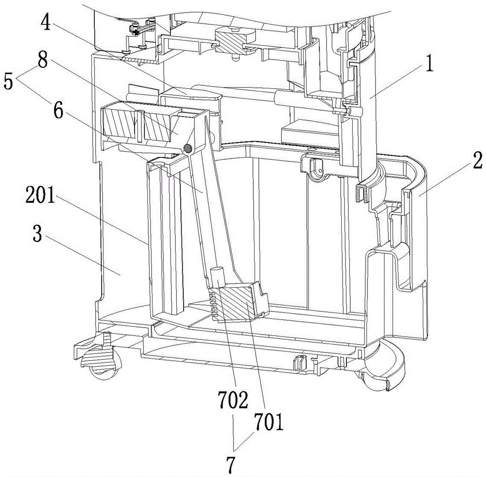
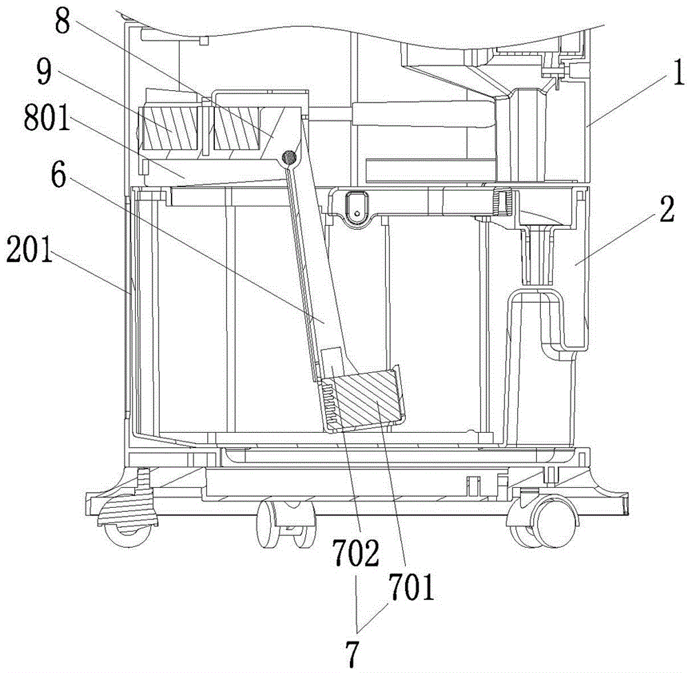
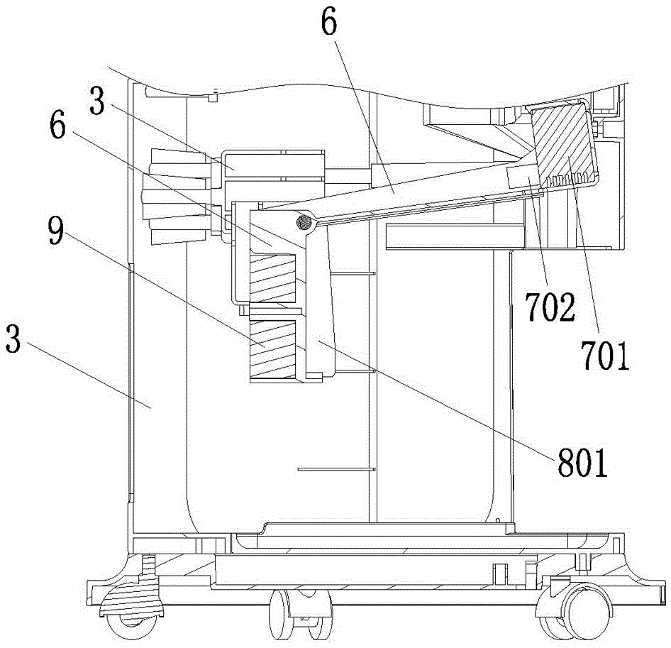
[0025] Such as Figure 1 to Figure 5 As shown, a water pump reset structure for a cooling fan includes a body 1, a water tank installation cavity 3 suitable for the push-pull installation of the water tank 2 is provided at the lower part of the body 1, and a connecting seat 4 is installed on the inside of the body 1 above the water tank installation cavity 3 , the connecting seat 4 is rotatably connected with a water pump bracket 5, and one end of the water pump bracket 5 is extended with a support arm 6, and a water pump assembly 7 is installed on the support arm 6, and the other end of the water pump bracket 5 is extended with a counterweight seat 8, and the counterweight seat 8 is installed with a counterweight 9, and the weight of the counterweight 9 is greater than the weight of the water pump assembly 7. This structure is simplified to the greatest extent th...


PUM


Abstract

The invention discloses a water pump reset structure for a cooling fan. The water pump reset structure comprises a machine body. A water tank mounting cavity suitable for push-pull type mounting of a water tank is formed in the lower portion of the machine body. A connecting seat is mounted at the position, above the water tank mounting cavity, of the inner side of the machine body. The connecting seat is rotationally connected with a water pump support. One end of the water pump support extends to form a supporting arm. A water pump assembly is mounted on the supporting arm. The other end of the water pump support extends to form a balance weight seat. A balance weight is mounted on the balance weight seat, and the weight of the balance weight is larger than that of the water pump assembly. The structure is simplified to the largest degree based on the wane principle, mechanical cooperation is simpler, and greater reliability is achieved during operating; the situation that due to the fact that the water pump support is in contact with water vapor for a long time, an elastic element rusts, and the reset structure fails is avoided; and due to the fact that parts are reduced, the total cost is reduced, and the yield returns are improved.

Description

technical field [0001] The invention relates to the field of cooling fans, in particular to a water pump reset structure for cooling fans. Background technique [0002] At present, the cooling fan is a new type of product after the electric fan. It can not only supply air, heat, purify, but also humidify, and cool down through the evaporation of water, so that the cooling effect can reach the comfort level of the air conditioner, and consumes less energy. It can be small, so it is loved by people. [0003] However, this type of product requires the user to add water or replace the ice crystal box regularly, and the water tank and water curtain need to be cleaned after a period of use. It needs to be used at the bottom of the water tank, so when the water tank is pulled out, the water pump needs to be lifted first, or the water pump should be lifted while pulling out to avoid damage to the water pump structure. [0004] The published Chinese patent 201210224213.3 has provid...

Claims


Application Information

Patent Timeline
Patent Type & Authority Applications(China)
IPC IPC(8): F24F5/00F24F13/30
CPCF24F5/0007F24F13/30
Inventor 刘艳丽
Owner SHUNDE KINGTEC APPLIANCES CO LTD
Learn More