
Heat exchanger of oil heater

A technology of heat exchanger and oil heater, applied in the field of household electrical appliances, can solve the problems of insufficient cooling of heat sinks, burns, etc., and achieve the effects of avoiding burns, strengthening heat dissipation capacity, and increasing flow strength.

Active Publication Date: 2017-03-22
GD MIDEA ENVIRONMENT APPLIANCES MFG +1
View PDF4 Cites 9 Cited by
  • Summary
  • Abstract
  • Description
  • Claims
  • Application Information

AI Technical Summary

Problems solved by technology

However, the oil heat exchanger relies solely on the air insulation design in the air chamber, which cannot sufficiently cool the edge of the heat sink, and there is a risk of burns to the user during use.

Method used


Image

  • Heat exchanger of oil heater
  • Heat exchanger of oil heater
  • Heat exchanger of oil heater

Examples


Embodiment Construction

[0022] Embodiments of the invention are described in detail below, examples of which are illustrated in the accompanying drawings. The embodiments described below by referring to the figures are exemplary and are intended to explain the present invention and should not be construed as limiting the present invention.

[0023] In describing the present invention, it is to be understood that the terms "length", "upper", "lower", "vertical", "horizontal", "top", "bottom", "inner", "outer" etc. The indicated orientation or positional relationship is based on the orientation or positional relationship shown in the drawings, and is only for the convenience of describing the present invention and simplifying the description, rather than indicating or implying that the referred device or element must have a specific orientation, or in a specific orientation. construction and operation, therefore, should not be construed as limiting the invention.

[0024] In addition, the terms "first...


PUM


Abstract

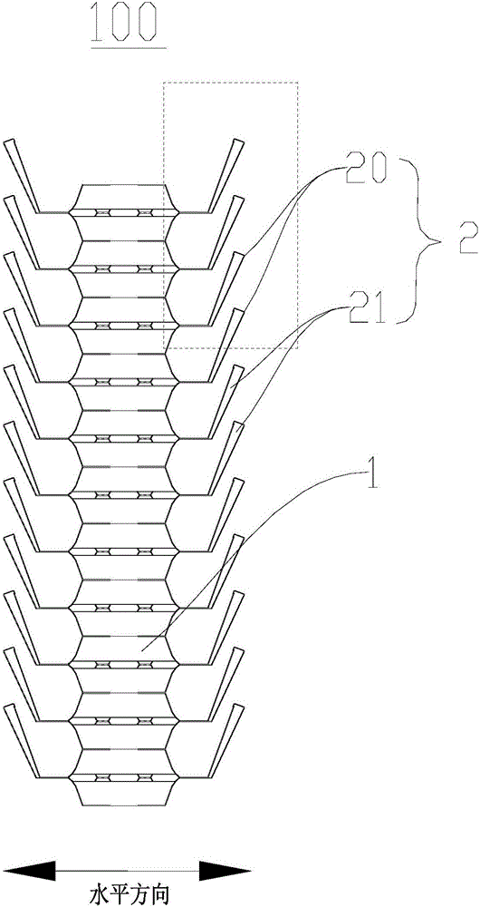
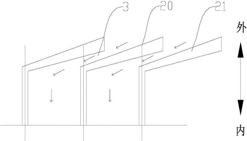
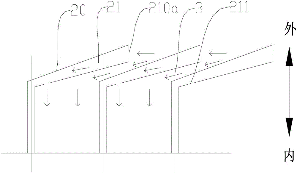
The invention discloses a heat exchanger of an oil heater. The heat exchanger comprises two oil pipes and multiple heat dissipation plates, wherein the two oil pipes are distributed vertically at an interval; and two ends of each heat dissipation plate are disposed on the two oil pipes respectively, an oil way channel communicating with the two oil pipes is disposed inside each heat dissipation plate, eat least one side edge of each heat dissipation plate is bent towards the other heat dissipation plate so as to form a bent part, bent parts with the same bending direction are disposed on the same side edge of at least two heat dissipation plates, and at least a part of one of the adjacent bent parts on the same side is located on the outer side of the other bent part so as to form an air flow channel. The heat exchanger of the oil heater disclosed by the invention has the advantages that flowing strength of air on the outer surface of the heat dissipation plates can be increased; the temperature on edges of the heat dissipation plates can be reduced; the heat dissipation capacity of the heat dissipation plates can be enhanced; and a user is prevented from being scalded during use of the heat exchanger of the oil heater.

Description

technical field [0001] The invention relates to the technical field of household electrical appliances, in particular to an oil-based heat exchanger. Background technique [0002] The working principle of the current oil heat exchanger is to use electric heating rods to heat the heat-conducting oil in the metal cavity, and then the high-temperature heat-conducting oil transfers heat to the surrounding air through the metal cavity and the cooling fins on the cavity to achieve heating for users. purpose goods. Generally, the higher the temperature of the metal cavity and the heat sink, the better the heat dissipation to the ambient air. [0003] A very thin air chamber is generally left on the edge of the heat sink of the oil-filled heat exchanger in the related art, and through holes are designed at regular intervals on the air chamber, and the air enters the air chamber through the through holes. The thermal conductivity of the heat sink is much lower than that of metal (g...

Claims


Application Information

Patent Timeline
Patent Type & Authority Applications(China)
IPC IPC(8): F28D1/053F28F3/04F28F13/02F24D13/04F24D19/00
CPCF24D13/04F24D19/00F28D1/053F28F3/042F28F13/02
Inventor 岳宝王文鹏陈小潭周伟平杜文波
Owner GD MIDEA ENVIRONMENT APPLIANCES MFG
Learn More