
Engine noise source identification method

An identification method and engine technology, applied in engine testing, machine/structural component testing, measurement of ultrasonic/sonic/infrasonic waves, etc., can solve the problem of large subjective influence, inability to obtain the contribution of noise sources, and inability to identify noise sources. Satisfy the overall accuracy and other issues

Inactive Publication Date: 2017-03-22
TIANJIN UNIV
View PDF3 Cites 15 Cited by
  • Summary
  • Abstract
  • Description
  • Claims
  • Application Information

AI Technical Summary

Problems solved by technology

Compared with traditional single signal processing methods, these methods have improved the accuracy of noise source identification, but there are still some shortcomings
These methods often measure and analyze a single noise at a single rotational speed. However, the noise source identification based on a single rotational speed and a single noise measurement point cannot meet the overall accuracy. The noise source identification method based on independent components and blind source separation can only pass Professional experience identifies some noise sources, and the contribution of noise sources cannot be obtained
Noise source identification based on AHP requires professional evaluation, and the result is greatly affected by the evaluator's subjectivity

Method used


Image

  • Engine noise source identification method
  • Engine noise source identification method
  • Engine noise source identification method

Examples


Embodiment Construction

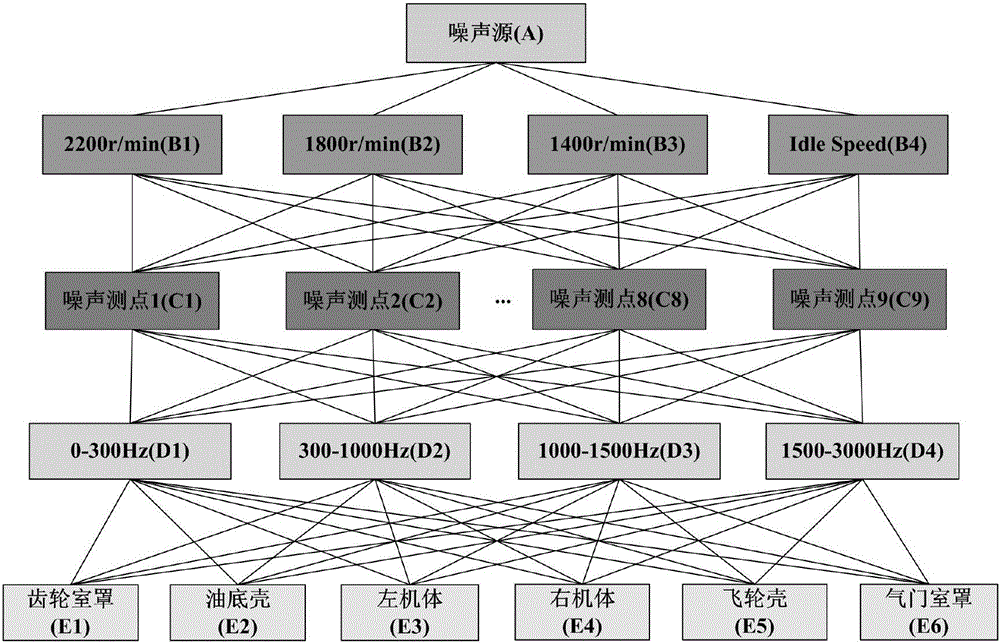
[0017] In view of the above problems, the purpose of the present invention is to overcome the deficiencies in the prior art, by constructing a hierarchical analysis tree, comprehensively considering the influence of different speed conditions, different measuring point positions and different noise frequency bands on the noise source identification results, and proposing by improving the AHP method An objective evaluation method to determine the pairwise comparison results is proposed, which eliminates the influence of the evaluator's subjective factors and improves the accuracy of noise source identification. Technical scheme of the present invention is as follows:

[0018] (1) First construct the hierarchical analysis tree of noise diagnosis, such as figure 1 As shown, it includes speed layer, noise measurement point layer, frequency band layer, and component layer. Each layer includes different elements. First, calculate the contribution of different components to different...


PUM


Abstract

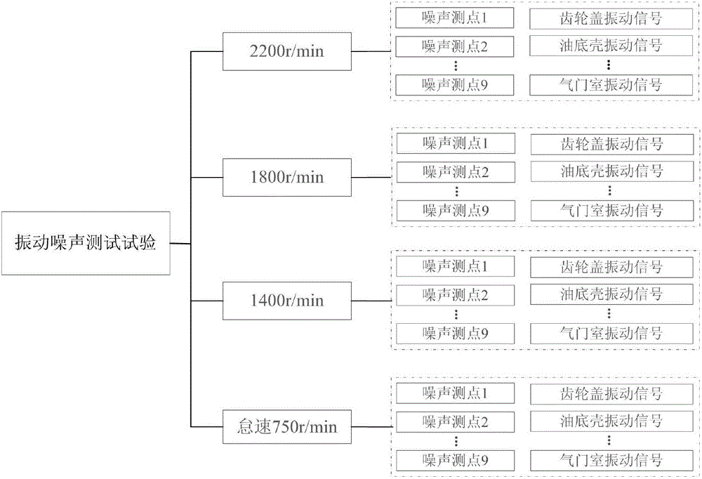
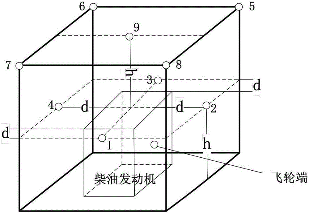
The invention relates to an engine noise source identification method. The method includes the following steps that: a noise diagnosis hierarchical analysis tree is constructed; the surface vibration signals of different components and corresponding engine surrounding noise signals are acquired through a vibration noise test; the noise signals are decomposed into different IMF components through an EEMD method, the IMF components are divided into different frequency bands according to the distribution of energy in the time-frequency spectra of the IMF components; based on the vibration signals of the different components and the IMF components of different frequency bands in the noise signals, calculation is carried out with a coherent power spectrum analysis method so as to obtain input coherent power spectra, and different input coherent power spectra are corresponding to different diesel engine components; paired comparative judgment matrixes are built according to the numerical values of the different input coherent power spectra, and the weights of the different components are calculated, and the weights of the different frequency bands are obtained; and different combined weight matrices are constructed according to the weights of the different components and the weights of the different frequency bands.

Description

technical field [0001] The invention relates to a method for identifying an engine noise source. Background technique [0002] As a necessary prerequisite for engine noise reduction, many noise source identification methods have been applied in research and engineering practice; there are many types of noise source identification methods, and the identification accuracy and test cost are also different; traditional noise source identification methods are relatively mature, but Relatively common, lacking in recognition accuracy and systematicness. The noise source identification method based on acoustic array technology has great advantages in terms of visibility and intuition, but this technology requires the support of relatively expensive test equipment, and it is slightly insufficient in the analysis of frequency domain results. Therefore, noise source identification methods based on signal processing have been developed rapidly and widely used in related fields. For th...

Claims


Application Information

Patent Timeline
Patent Type & Authority Applications(China)
IPC IPC(8): G01M15/00G01H17/00
CPCG01M15/00G01H17/00
Inventor 王健张俊红
Owner TIANJIN UNIV
Learn More