Machine vision based full-automatic rotation printed product defect detection device
A defect detection and machine vision technology, which is applied in the field of automatic rotary printing product defect detection device, achieves the effect of short cycle, precise positioning and reduced movement
- Summary
- Abstract
- Description
- Claims
- Application Information
AI Technical Summary
Problems solved by technology
Method used
Image
Examples
Embodiment example 1
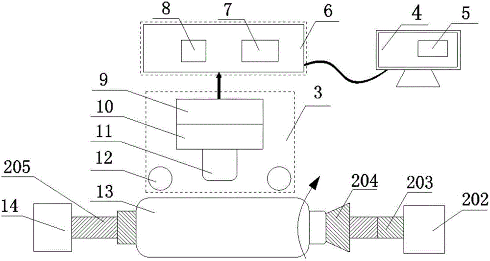
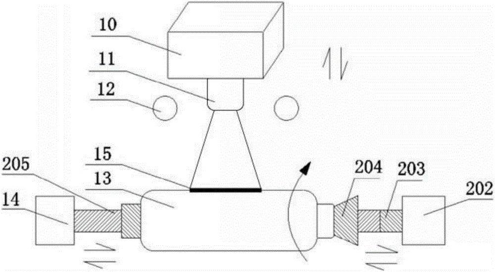
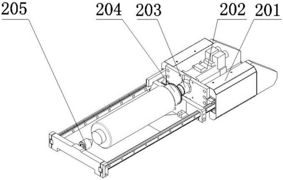
[0039] refer to Figure 6 1. Oval bottle printing defect detection: the light source 12 on the fixed frame is turned on to provide light to the linear CCD camera 10 . The feeding manipulator 1 clamps the oval bottle printed product and transfers it to the product clamping and rotating system 2 by the conveyor belt. The product clamping cylinder 14 pushes the top block 205 and the clamp 204 to jointly clamp the printed oval bottle to be tested. With the servo motor The rotation of the output shaft of 202 rotates, and the encoder 203 assembled on the output shaft of the servo motor 202 also rotates with the rotation of the output shaft of the servo motor 202, and moves synchronously with the printed elliptical bottle 13. The encoder 203 sends a pulse every time, Just control the exposure of the linear array CCD camera 10 once, the encoder 203 rotates once, and the linear array CCD camera 10 also completes the acquisition of an image at the same time, realizing the synchronizatio...
Embodiment example 2
[0041] refer to Figure 7 , Printing defect detection of printed special-shaped bottles: the light source 12 on the fixed frame is turned on to provide light to the linear CCD camera 10 . The feeding manipulator 1 clamps the printed special-shaped bottle and transfers it to the product clamping and rotating system 2 by the conveyor belt. The product clamping cylinder 14 pushes the top block 205 and the clamp 204 to clamp the printed special-shaped bottle to be inspected. With the servo The rotation of the output shaft of the motor 202 rotates, and the encoder 203 assembled on the output shaft of the servo motor 202 also rotates with the rotation of the output shaft of the servo motor 202, and moves synchronously with the printed special-shaped bottle 13. The encoder 203 sends a pulse every time , just control the line array CCD camera 10 to expose once, the encoder 203 rotates a circle, and the line array CCD camera 10 also completes the acquisition of an image at the same tim...
Embodiment example 3
[0043] refer to Figure 8 , Printing defect detection on the printed spherical surface: the light source 12 on the fixed frame is turned on to provide light to the linear CCD camera 10 . The feeding manipulator 1 clamps the printed spherical product and transfers it to the product clamping and rotating system 2 by the conveyor belt. The product clamping cylinder 14 pushes the top block 205 and the clamp 204 to jointly clamp the printed spherical product to be tested. With the servo The rotation of the output shaft of the motor 202 rotates, and the encoder 203 assembled on the output shaft of the servo motor 202 also rotates with the rotation of the output shaft of the servo motor 202, and moves synchronously with the spherical product 13. Every time the encoder 203 sends out a pulse, it controls The linear array CCD camera 10 exposes once, the encoder 203 rotates once, and the linear array CCD camera 10 also completes the acquisition of an image at the same time, realizing the...
PUM
 Abstract
Description
Claims
Application Information
 - R&D
- Intellectual Property
- Life Sciences
- Materials
- Tech Scout
- Unparalleled Data Quality
- Higher Quality Content
- 60% Fewer Hallucinations
Browse by: Latest US Patents, China's latest patents, Technical Efficacy Thesaurus, Application Domain, Technology Topic, Popular Technical Reports.
© 2025 PatSnap. All rights reserved.Legal|Privacy policy|Modern Slavery Act Transparency Statement|Sitemap|About US| Contact US: help@patsnap.com


