
An in-situ loading device based on scanning electron microscope

A technology of scanning electron microscopy and in-situ loading, which is applied in the direction of scanning probe technology and instruments, can solve the problems that there is no supporting loading device for scanning electron microscope, achieve large load and high frequency fatigue loading, and improve the effect of measurement accuracy

Inactive Publication Date: 2019-04-30
UNIV OF JINAN
View PDF7 Cites 0 Cited by
  • Summary
  • Abstract
  • Description
  • Claims
  • Application Information

AI Technical Summary

Problems solved by technology

At present, there is no self-developed scanning electron microscope supporting loading device

Method used


Image

  • An in-situ loading device based on scanning electron microscope
  • An in-situ loading device based on scanning electron microscope

Examples


Embodiment approach

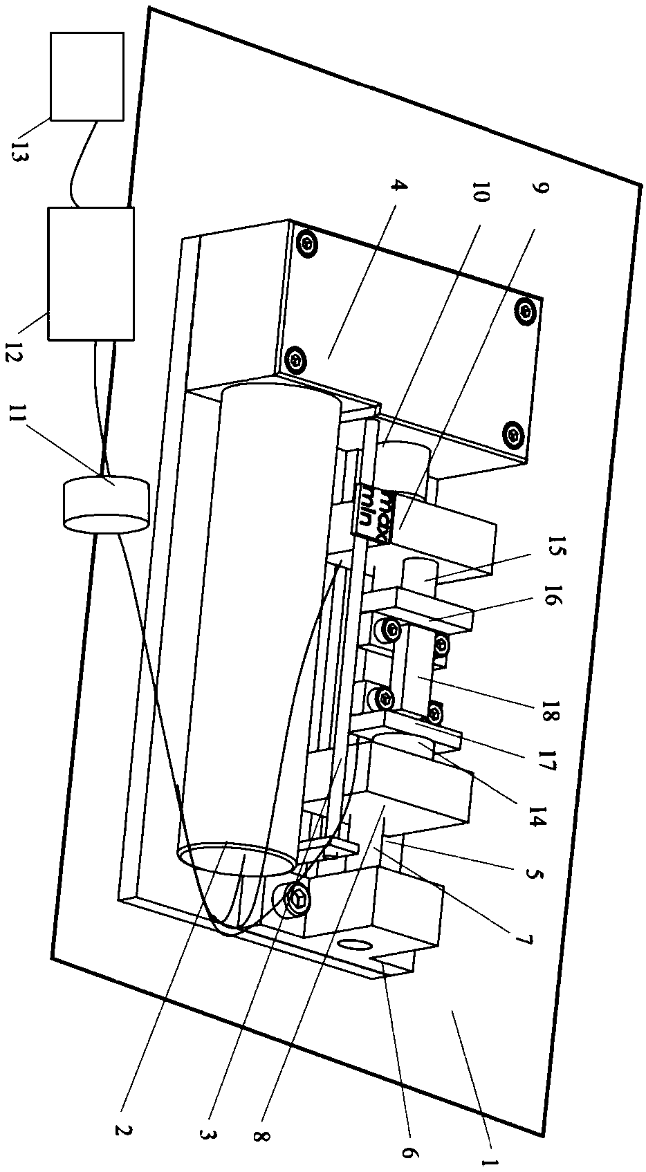
[0021] Such as figure 1 As shown, an in-situ loading device based on a scanning electron microscope according to the present invention includes a fixed plate 1, a motor 2, a grating displacement meter 3, a transmission device 4, a slider guide rail 5, a bearing seat 6, a bidirectional Ball screw 7, first adapter block 8, second adapter block 9, coupling 10, control box 11, computer 12, sealing flange with transmission line 13, force sensor 14, combined piezoelectric ceramics 15, The first clamping device 16, the second clamping device 17 and the test piece 18, and all the components are placed on the fixed plate 1 except the control box 11, the computer 12, and the sealing flange 13 with transmission lines.

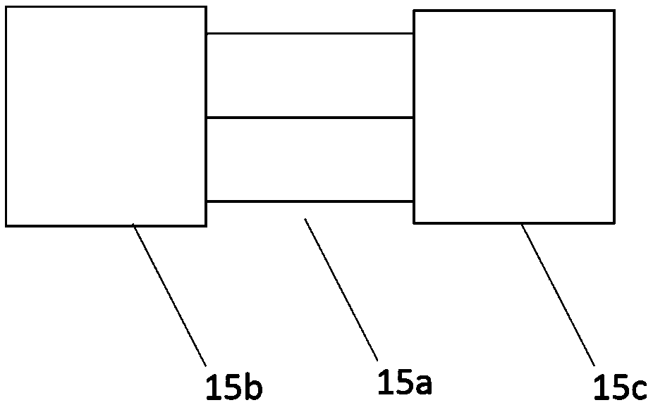
[0022] The motor 2 is connected to the transmission device 4 through a keyway, and the transmission device 4 is connected to the bidirectional ball screw 7 with a nut through a coupling 10 . Such as figure 2 As shown, the combined piezoelectric ceramic 15 is composed o...


PUM


Abstract

An in-situ loading device based on a scanning electron microscope, the motor is connected to the transmission device, and the transmission device is connected to the bidirectional ball screw; The connection block is connected to the second transfer block, and the second transfer block is connected to the first clamping device, and the first transfer block is connected to the second clamping device through a force sensor; the grating displacement gauge is connected to the first transfer block ;The control lines of the motor, displacement gauge and force sensor are connected to the control box through the sealed flange with the transmission line, and the control line of the control box is connected with the computer; the signal acquisition and control are realized through the computer; the two ends of the test piece They are respectively fixed on the first clamping device and the second clamping device, and the test piece is loaded through the overall mechanism. The invention can test the static and dynamic loading performance of uniaxial stress on typical test pieces of metal or non-metal materials under the scanning electron microscope, so as to realize dynamic, low-frequency fatigue or high-frequency fatigue loading.

Description

technical field [0001] The invention relates to an in-situ loading device based on a scanning electron microscope, which is a special loading device suitable for observation under a scanning electron microscope, and belongs to the technical field of component deformation measurement. Background technique [0002] The macro damage of materials is often caused by the accumulation of micro failures. For example, the damage of metal polycrystalline materials often starts from grain boundary fracture. In addition, the research on the macro mechanical properties of macro materials has been relatively mature. At present, relevant scholars will research the field of view Gradually turned to the study of micro-scale mechanical properties of materials, which inevitably involves the problem of micro-deformation measurement. The key to realizing microscopic deformation measurement is to improve the spatial resolution and displacement sensitivity of measurement. In recent years, the dev...

Claims


Application Information

Patent Timeline
Patent Type & Authority Patents(China)
IPC IPC(8): G01Q10/00
CPCG01Q10/00
Inventor 李艳杰舒庆琏赵国华杨令强韩光
Owner UNIV OF JINAN
Learn More