
An automatic termination device for copper legs of a power cord

A technology of power cords and power devices, which is applied in the direction of circuits, electrical components, circuit/collector components, etc., can solve difficult problems, and achieve the effect of simplified crimping and automatic crimping

Active Publication Date: 2018-08-07
常熟利星光电科技有限公司
View PDF1 Cites 0 Cited by
  • Summary
  • Abstract
  • Description
  • Claims
  • Application Information

AI Technical Summary

Problems solved by technology

Such a production process is difficult to achieve both economical and efficient production

Method used


Image

  • An automatic termination device for copper legs of a power cord
  • An automatic termination device for copper legs of a power cord
  • An automatic termination device for copper legs of a power cord

Examples


Embodiment Construction

[0024] The present invention will be further described in detail below in conjunction with the accompanying drawings and specific embodiments.

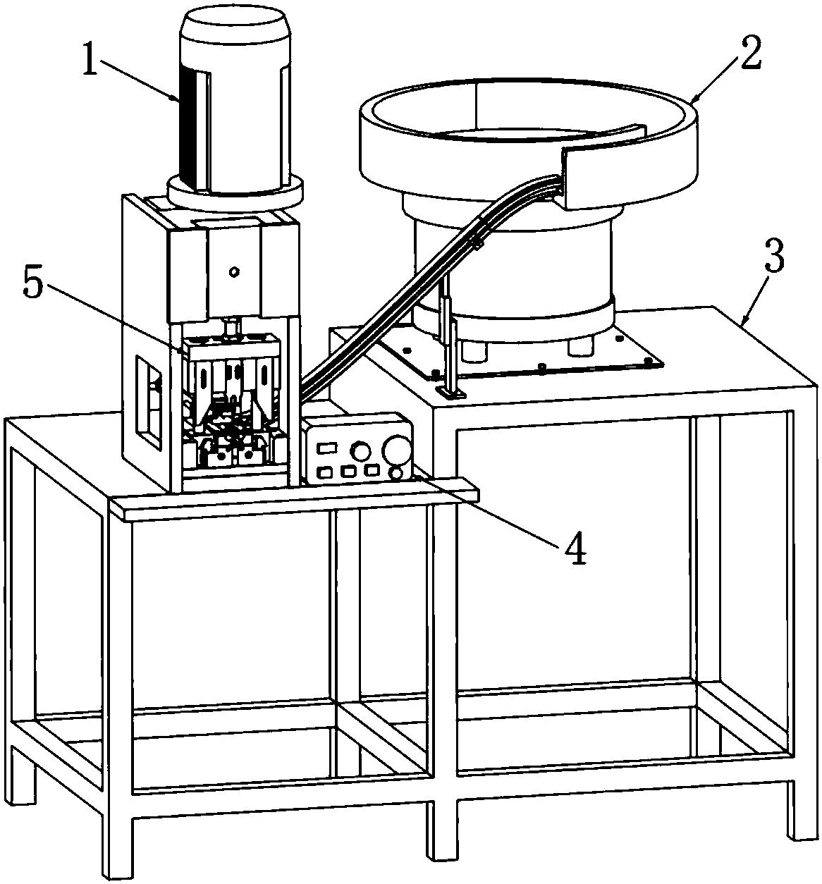
[0025] Such as figure 2 As shown in the figure, an automatic end-typing device for copper legs of a power cord includes a terminal machine 1 , a vibrating plate 2 , a control system 4 and a feeding and crimping system 5 . The control system 4 can adjust the material pushing device 7 independently, so that it is convenient to debug the situation of individual material jams. The vibrating disc 2 is installed on the frame 3, and the vibrating disc 2 passes through the material guide belt 9 (as image 3 Shown) transport copper inner frame (copper inner frame has copper feet).

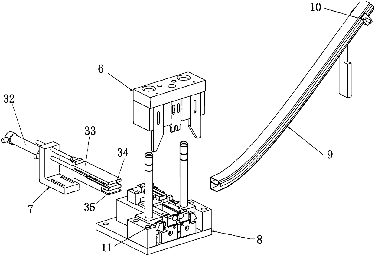
[0026] Such as Figure 3-9 As shown, the feeding crimping system 5 includes a pushing device 7, an upper crimping body 6 and a lower crimping body 8, the lower crimping body 8 is located below the upper crimping body 6, and the pushing device 7 is located at th...


PUM


Abstract

The invention discloses an automatic terminal crimping device for a copper foot of a power line. The device comprises a push device, an upper crimping body and a lower crimping body, wherein the lower crimping body is located at the lower part of the upper crimping body; the push device is located on the edge of the lower crimping body; a crimping part comprises an upper blade, a left press block, a right press block, a left blade, a right blade, a left sliding block, a right sliding block, a spring and a lower blade; when the copper foot is transported to a crimping position, the upper blade, the left press block and the right press block move downwards, the left press block and the right press block are in contact with the left sliding block and the right sliding block; and the left sliding block and the right sliding block convert up-and-down acting force into left-and-right acting force through slopes under the extrusion of the left press block and the right press block, the left sliding block and the right sliding block move towards the inner side and drive the left blade and the right blade to be riveted, and the upper blade descends and is riveted in the up-and-down direction, thereby completing crimping in two directions. According to the automatic terminal crimping device, the whole crimping process can be completed only by one device and one operator, one-time continuous and automatic crimping of the three-prong copper foot is achieved and crimping of the three-prong copper foot is simplified.

Description

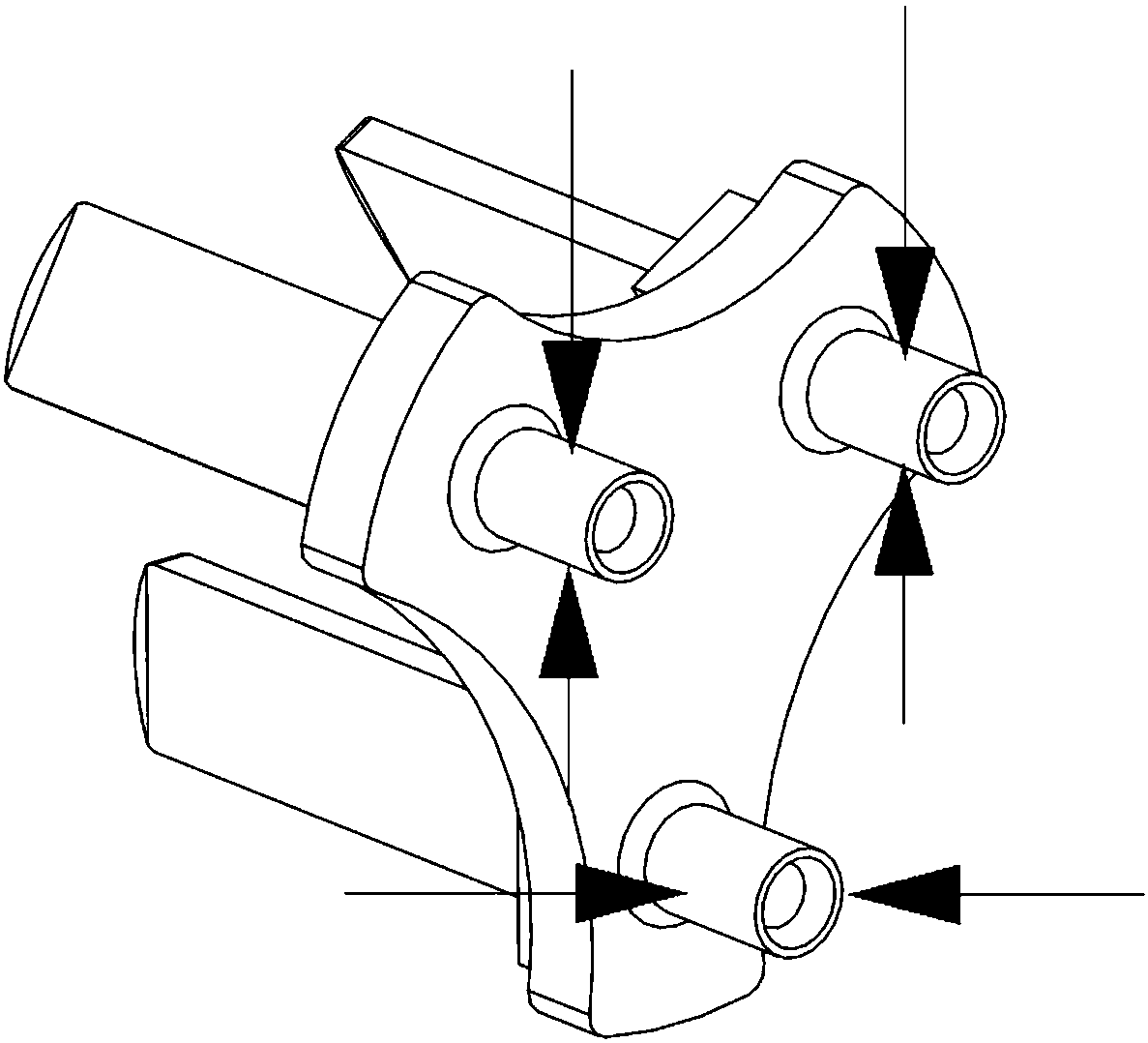
technical field [0001] The invention relates to a device for automatically terminating a copper leg of a power cord, in particular to an automatic device for terminating a copper leg of a power cord with three copper pins, and belongs to the technical field of automatic plug production. Background technique [0002] In the crimping process of three-plug copper feet, the general method of crimping is: the employee picks up a copper foot, puts the copper wire of the line into the copper foot, and then puts the copper foot into the positioning groove of the copper foot knife mold, Then drive the copper foot knife die to crimp the copper feet through the terminal machine, and finally take out the crimped copper feet from the positioning groove. For example, the patent document of application publication number CN103972767A discloses an automatic transmission and riveting device for power cord plug parts with a plastic body, which includes a terminal machine, a feeding device, a ...

Claims


Application Information

Patent Timeline
Patent Type & Authority Patents(China)
IPC IPC(8): H01R43/055
CPCH01R43/055
Inventor 庄锦强沈睿田军
Owner 常熟利星光电科技有限公司
Learn More