Wire end crimping method for electric power high-voltage wire harness

A high-voltage wire harness and wire head technology, applied in circuits, connections, electrical components, etc., can solve problems such as cumbersome operations, misalignment of sub-wires, and inability to accurately control the crimping position.

Inactive Publication Date: 2021-09-03
熊芳
View PDF4 Cites 0 Cited by
  • Summary
  • Abstract
  • Description
  • Claims
  • Application Information

AI Technical Summary

Problems solved by technology

[0005] In order to overcome the problem that the exposed sub-wires at one end of the high-voltage wire harness in the prior art need to be processed sequentially before leaving the factory, manual operations are required to perform crimping operations on the sub-wires in sequence, that is, manually insert multiple sub-wires into the crimping machine in sequence In the process of crimping, and before crimping, it is necessary to manually put the thread end sleeve on the outside of the sub-wire, which is cumbersome to operate; and the crimping position cannot be accurately controlled during the manual operation, which leads to different crimping positions of different sub-wires , resulting in subsequent wiring through this connector, different connection positions of different sub-wires will occur, and the problem of misalignment of sub-wires will occur, which will lead to the problem that the sub-wires cannot be stably connected for power transmission. At the same time, the sub-wires are arranged in a ring, which is not easy to distinguish and crimp sequentially. In the case of workers' misuse, it will cause secondary crimping of some sub-wire joints, resulting in a decrease in the strength of the sub-wire joints and a shortened service life. Technical problem to be solved: provide a method for crimping the end of the electric high-voltage wire harness

Method used


Image

  • Wire end crimping method for electric power high-voltage wire harness
  • Wire end crimping method for electric power high-voltage wire harness
  • Wire end crimping method for electric power high-voltage wire harness

Examples


Embodiment

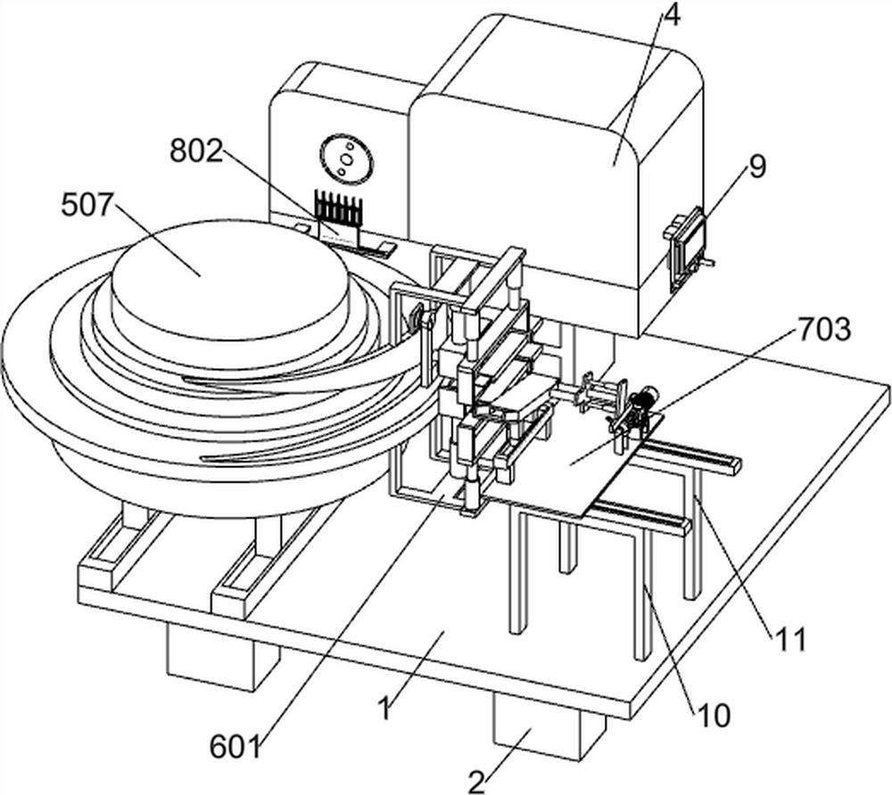
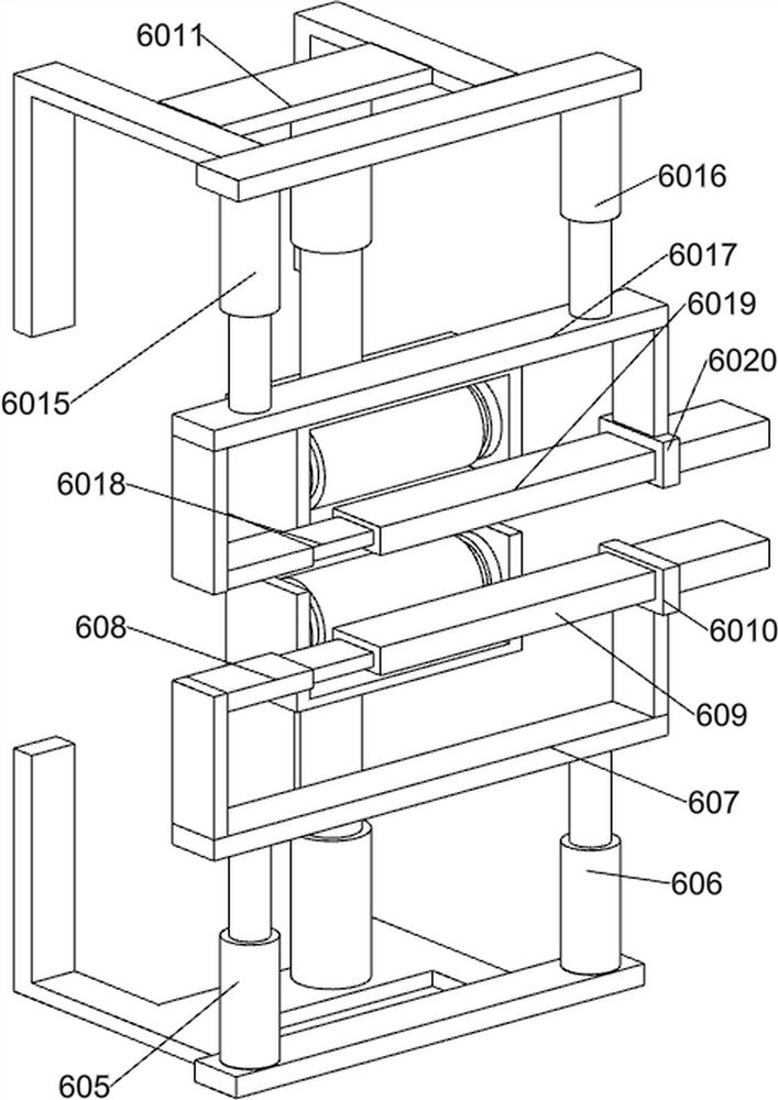
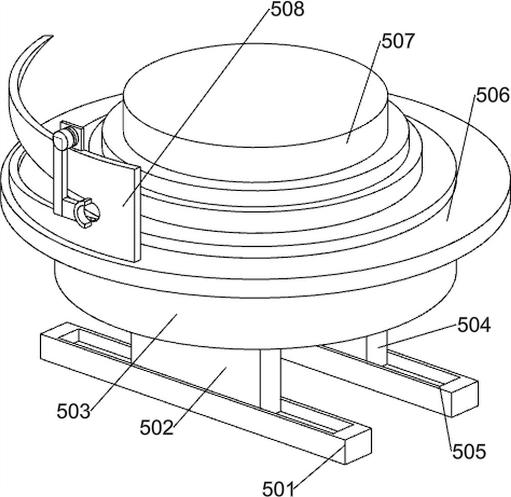
[0038] A method for crimping wire ends of electric high-voltage wire harnesses, according to Figure 1-3 As shown, the following processing equipment is used in the crimping method of the wire end of the high-voltage electric wire harness. The processing equipment includes a working machine plate 1, a supporting foot 2, a first supporting foot 3, a crimping machine 4, a wire harness fixing system, and a crimping terminal Control system, line head sorting and crimping system, operation control panel 9, second support stand 10 and third support stand 11; the lower part of the working machine plate 1 is welded to the support foot 2; the upper part of the working machine plate 1 is connected to the first support The tripod 3 is welded; the top of the first support tripod 3 is bolted to the crimping machine 4; the wiring harness fixing system is installed above the working machine tool board 1; the crimping terminal control system is connected to the side of the wiring harness fixin...


PUM


Abstract

The invention belongs to the field of high-voltage wire harnesses and relates to a wire end crimping method for an electric power high-voltage wire harness. The invention aims to provide the wire end crimping method for the electric power high-voltage wire harness. According to the wire end crimping method for the electric power high-voltage wire harness,processing equipment is adopted, and the processing equipment comprises a crimping machine, a wire harness fixing system, a crimping wire end control system, a wire end sequencing crimping system, an operation control screen, a second supporting foot stool, a third supporting foot stool and the like; the lower portion of a working machine tool plate is welded to supporting bottom feet. According to the wire end crimping method for the electric power high-voltage wire harness of the invention, automatic crimping and bunching of the internal sub-wires of the high-voltage wire harness are realized, single crimping of the sub-wires is ensured through a single straightening mode of overall bending of the sub-wires, the problem of secondary crimping caused by disorder of part of the sub-wires is avoided, and identical crimping positions and sequential arrangement and automatic crimping of the sub-wires are ensured.

Description

technical field [0001] The invention relates to the field of high-voltage wire harnesses, in particular to a method for crimping wire ends of electric high-voltage wire harnesses. Background technique [0002] High-voltage lines usually refer to transmission lines that carry voltages above 10kV. According to GB / T2900.50-2008, definition 2.1 stipulates that high voltage usually does not contain 1000V. The voltage levels of China's domestic high-voltage transmission lines are generally divided into: 35kV, 110kV, 220kV, 330kV, 500kV, 750kV, etc. [0003] At present, before the high-voltage wire harness in the prior art leaves the factory, the exposed sub-wires at one end need to be processed sequentially, and manual operation is required to perform crimping operations on the sub-wires in sequence, that is, manually insert multiple sub-wires into the crimping machine in sequence. In the process of crimping, and before crimping, it is necessary to manually put the thread end sl...

Claims


Application Information

Patent Timeline
Patent Type & Authority Applications(China)
IPC IPC(8): H01R43/048
CPCH01R43/048
Inventor 熊芳
Owner 熊芳
Why Eureka
Try Eureka