Non-contact type dynamic power supply system coil for trains in rail transit

A rail transit train, non-contact technology, applied in circuits, inductors, motor vehicles, etc., can solve problems such as unfavorable system parameter design, affecting system efficiency, etc., to reduce reactive power output, stabilize the coupling coefficient, and improve the system. The effect of power factor

Inactive Publication Date: 2017-03-22
SOUTHWEST JIAOTONG UNIV
View PDF7 Cites 14 Cited by
  • Summary
  • Abstract
  • Description
  • Claims
  • Application Information

AI Technical Summary

Problems solved by technology

But there are still problems: there is a coupling relationship between the energy transmitting coils of each segment of the same polarity, which is not conducive to the design of system parameters. At the same time, the system is in a non-resonant working condition, which affects the system efficiency.

Method used


Image

  • Non-contact type dynamic power supply system coil for trains in rail transit
  • Non-contact type dynamic power supply system coil for trains in rail transit
  • Non-contact type dynamic power supply system coil for trains in rail transit

Examples


Embodiment Construction

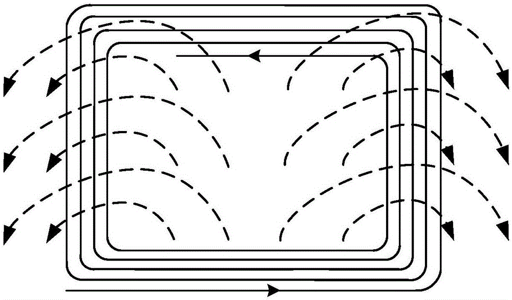
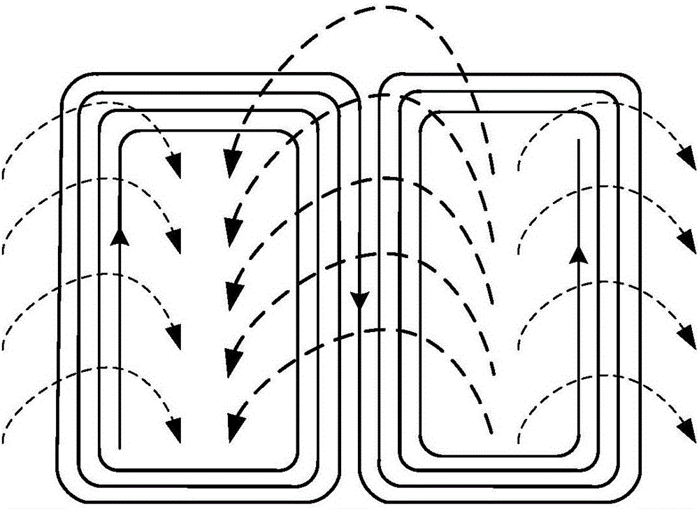
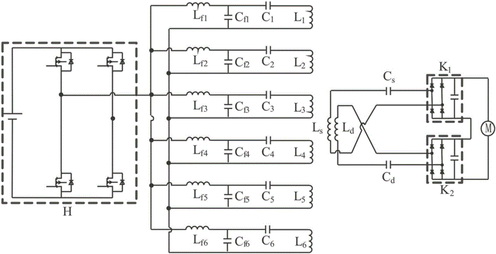
[0022] The technical solutions and technical effects of the present invention will be further described in detail below in conjunction with the accompanying drawings and specific embodiments. A non-contact dynamic power supply system coil for a rail transit train, including an energy transmitting coil laid along the track and an energy pickup coil installed at the bottom of the train. The coil is connected to the bipolar coil on the transmitting side, and the direction of the main magnetic field generated by the bipolar coil on the transmitting side is perpendicular to the forward direction of the train. The compensation filter circuits where each energy transmitting coil is located are connected in parallel to the high-frequency AC power supply H; the energy pickup coil includes a long One pickup-side unipolar coil and one pickup-side bipolar coil with the same width as the energy transmitting coil, the pickup-side unipolar coil is connected in series with the compensation cap...


PUM


Abstract

The invention discloses a non-contact type dynamic power supply system coil for trains in the rail transit. The coil comprises energy emission coils laid along tracks and energy picking coils installed at the bottoms of the trains. Each energy emission coil comprises multiple segments of uni-polarity coils and dual-polarity coils, which are equal in length and width and successively alternatively laid. A compensation filtering loop where the corresponding energy emission coil is arranged is parallelly connected to a high-frequency alternating-current power supply H. The energy picking coils comprise a uni-polarity coil and a dual-polarity coil, which are equal with the energy emission coils in length and width. The uni-polarity coils are serially connected with a capacitor and then parallelly connected to the input end of a rectifier K1. The dual-polarity coils are serially connected with a capacitor and then parallelly connected to the input end of a rectifier K2. The output end of the rectifier K1 and the output end of the rectifier K2 are serially connected and then connected to a motor G. According to the invention, decoupling of the energy emission coils is achieved; and the energy picking coils pick stable induced electromotive force during a moving process.

Description

technical field [0001] The invention relates to the technical field of inductive power transmission, in particular to a non-contact dynamic power supply system coil for rail transit trains. Background technique [0002] The inductive power transfer technology transmits electric energy from the energy emitting device to the energy pickup device in a non-contact manner through the high-frequency magnetic field coupling between the energy transmitting coil and the energy pickup coil. Compared with the traditional way of taking electricity by direct physical contact with conductors, inductive power transmission technology has the advantage that because the coil is not directly exposed to the air, the power transmission process is not affected by dirt, ice, water and other chemicals , effectively improving the security and reliability of power supply, and has a good application prospect. [0003] The structure and working process of the inductive power transmission system are as...

Claims


Application Information

Patent Timeline
Patent Type & Authority Applications(China)
IPC IPC(8): H02J50/12H02J5/00B60L9/00H01F38/14
CPCB60L9/00B60L2200/26H01F38/14H01F2038/143H02J5/005Y02T10/72
Inventor 麦瑞坤林天仁李勇李宏超何正友
Owner SOUTHWEST JIAOTONG UNIV
Why Eureka
Try Eureka