Novel power electronic traction transformer topological structure and control method thereof

A technology of traction transformers and power electronics, which is applied in the direction of adjusting electrical variables, control/regulation systems, instruments, etc., and can solve problems such as high power and voltage levels, insignificant increase in power density of traction transformers, and design difficulties

Active Publication Date: 2017-03-22
BEIJING JIAOTONG UNIV
View PDF5 Cites 26 Cited by
  • Summary
  • Abstract
  • Description
  • Claims
  • Application Information

AI Technical Summary

Problems solved by technology

However, for the second type of topology, due to the limited number of cascaded cells, the power and voltage levels of each cell are still high
Therefore, for isolated DC / DC converters, the selection of switching devices usually requires the selection of high-voltage IGBTs of 6.5kV or 3.3kV, which greatly limits the further improvement of switching frequency; at the same time, medium / high frequency transformers are insulated Restricted by factors such as power level and heat dissipation, on the one hand, the design is more difficult, and on the other hand, the power density of the traction transformer is not significantly improved.

Method used


Image

  • Novel power electronic traction transformer topological structure and control method thereof
  • Novel power electronic traction transformer topological structure and control method thereof
  • Novel power electronic traction transformer topological structure and control method thereof

Examples


Embodiment Construction

[0041] In the following, a new power electronic traction transformer topology and its control method will be described in detail in combination with Figures 1-6. It should be emphasized that the following description is only exemplary and not intended to limit the scope of the invention and its application.

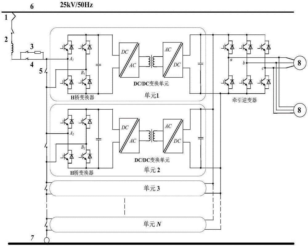
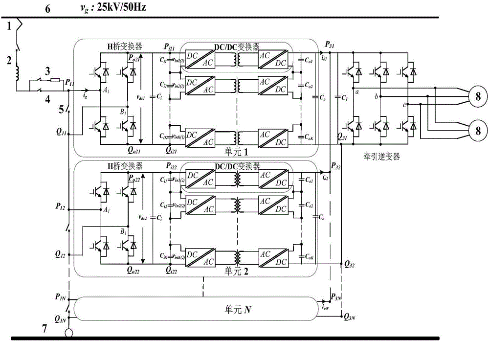
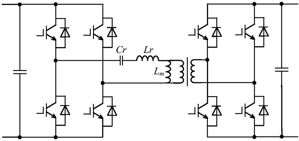
[0042] A new power electronic traction transformer topology, including N power conversion units; the power conversion unit includes an H-bridge converter and a medium / high-frequency isolated DC / DC conversion unit; the N H-bridge converters form N A cascaded H-bridge converter; the medium / high frequency isolated DC / DC conversion unit includes K DC / DC converters;

[0043] The input ends of the N power conversion units are connected in series, and the output ends are connected in parallel; the input ends of the N-level cascaded H-bridge converters are connected in series, and the output ends are not connected to each other; the N DC / DC conversion units The input ends are co...


PUM


Abstract

The invention discloses a novel power electronic traction transformer topological structure and a control method thereof. A novel power electronic traction transformer comprises N power transformation units. Each power transformation unit comprises an H bridge converter and a middle/high frequency isolated-type DC/DC conversion unit. The N H bridge converters for an N-grade cascaded H bridge converter, and the middle/high frequency isolated-type DC/DC conversion unit comprises K DC/DC converters. Input ends of the N power transformation units are connected in series and output ends of the N power transformation units are connected in parallel. Input ends of the N-grade cascaded H bridge converter are connected in series, and output ends of the N-grade cascaded H bridge converter are disconnected. Input ends of the N DC/DC conversion units are connected with the output ends of the N-grade cascaded H bridge converter, and output ends of the N DC/DC conversion units are connected in parallel. Input ends of the K DC/DC converters are connected in series, and output ends of the K DC/DC converters are connected in series. The power balance control of the novel power electronic traction transformer comprises three parts: the direct current output voltage balance control of each H bridge converter, the output current balance control of each middle/high frequency isolated-type DC/DC conversion unit, and the input voltage balance control of each DC/DC converter of each middle/high frequency isolated-type DC/DC conversion unit.

Description

technical field [0001] The invention belongs to the field of traction drive systems of high-speed EMUs, and in particular relates to a novel power electronic traction transformer topology structure and a control method thereof. Background technique [0002] As the traction power of high-speed EMUs and the energy source of auxiliary power supply system, the traction drive system is one of the most critical systems in high-speed EMUs. At present, high-speed EMUs generally use power-frequency traction transformers to obtain electric energy. After step-down conversion, single-phase power-frequency AC voltages are obtained, and then rectified by four-quadrant PWM rectifiers to obtain intermediate DC voltages. Finally, controllable DC voltages are obtained through traction inverters. The three-phase alternating current, and then realize the control of the traction motor. However, power frequency traction transformers are large in size and weight, low in efficiency, and low in pow...

Claims


Application Information

Patent Timeline
Patent Type & Authority Applications(China)
IPC IPC(8): H02M5/458H02M3/335
CPCH02M3/33523H02M5/458H02M1/0074H02M1/0077H02M1/0083
Inventor 刘建强张捷频杨景熙赵楠符里
Owner BEIJING JIAOTONG UNIV
Why Eureka
Try Eureka