Real motion estimation method and device

A technology of real motion and motion vector, which is applied in the field of image processing, can solve problems such as the inability to quickly and accurately converge motion vectors, and achieve the effects of increasing speed, ensuring continuity, and increasing the speed of motion convergence

Active Publication Date: 2019-09-06
SPREADTRUM COMM (SHANGHAI) CO LTD
View PDF6 Cites 0 Cited by
  • Summary
  • Abstract
  • Description
  • Claims
  • Application Information

AI Technical Summary

Problems solved by technology

However, this scanning order will cause the motion vector to converge along the order from top to bottom or from left to right, and cannot quickly and accurately converge to the real motion vector

Method used


Image

  • Real motion estimation method and device
  • Real motion estimation method and device
  • Real motion estimation method and device

Examples


Embodiment Construction

[0042] In order to solve the above-mentioned problems existing in the prior art, the technical solution adopted in the embodiment of the present invention is to use the motion vectors corresponding to the centroids of multiple classes obtained by clustering the motion vectors of each sub-block of the previous frame image as the current frame image and output the global motion vector, which can save the amount of computation and improve the accuracy of the calculated global motion vector.

[0043] In order to make the above objects, features and advantages of the present invention more comprehensible, specific embodiments of the present invention will be described in detail below in conjunction with the accompanying drawings.

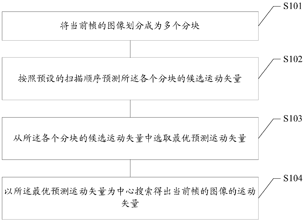
[0044] figure 1 A flow chart of a real motion estimation method in an embodiment of the present invention is shown. Such as figure 1 The real motion estimation method shown may include:

[0045] Step S101: Divide the image of the current frame into mu...


PUM


Abstract

A real motion estimation method and device, the method comprising: dividing the image of the current frame into a plurality of sub-blocks; predicting the candidate motion vectors of the respective sub-blocks according to a preset scanning sequence, the preset scanning sequence includes : Divide the image of the current frame into more than one sub-image along the horizontal direction; for the same sub-image, the block of the first line of scanning is from left to right and the blocks of adjacent lines are reversed. scanning order; for two adjacent sub-images, adopt a scanning order in which the row scanning order is reversed; select the optimal predicted motion vector from the candidate motion vectors of each sub-block; search for the optimal predicted motion vector Get the motion vector of the image for the current frame. The above solution can improve the speed and accuracy of motion vector estimation.

Description

technical field [0001] The present invention relates to the technical field of image processing, in particular to a real motion estimation method and device. Background technique [0002] At present, the codec technology in video transmission can obtain a high compression ratio. However, in order to adapt to some network bandwidth limitations, the temporal and spatial resolution of the video signal is usually reduced to reduce the amount of data. In the time domain, frame skipping at the encoding end can be used. accomplish. However, it will inevitably cause video motion discontinuity and image quality degradation at the decoding end, especially in fast moving and complex scenes. [0003] In order to solve the above problems, the original frame rate can be restored by adopting the video frame insertion technology at the decoding end, that is, the frame rate conversion technology, so as to improve the subjective visual effect of the video image. Video frame insertion techno...

Claims


Application Information

Patent Timeline
Patent Type & Authority Patents(China)
IPC IPC(8): H04N19/176H04N19/51
Inventor 王森林福辉罗小伟徐晶明
Owner SPREADTRUM COMM (SHANGHAI) CO LTD
Why Eureka
Try Eureka