
Insert components for trimming gap areas

A technology for inserting components and gap areas, applied in furniture accessories, applications, household stoves, etc., can solve the problems of long production time and high production cost, and achieve the effect of reducing production time and cost, and simplifying the assembly process

Active Publication Date: 2019-07-23
LG ELECTRONICS INC
View PDF4 Cites 0 Cited by
  • Summary
  • Abstract
  • Description
  • Claims
  • Application Information

AI Technical Summary

Problems solved by technology

[0008] However, such plug-in assemblies must use many parts and require auxiliary assembly lines
Traditional insert components have the disadvantage of long production times and high production costs

Method used


Image

  • Insert components for trimming gap areas
  • Insert components for trimming gap areas
  • Insert components for trimming gap areas

Examples


Embodiment Construction

[0047] best practice

[0048] Referring to the accompanying drawings, a system for interworking between a cooking device and a kitchen device according to an embodiment of the present disclosure will be described in detail. Regardless of the reference numerals, the same or equivalent components may be provided with the same reference numerals, and descriptions thereof will not be repeated. For brief description with reference to the drawings, the size and shape of elements shown in the drawings may be exaggerated or reduced, and it should be understood that the embodiments presented herein are not limited by the drawings.

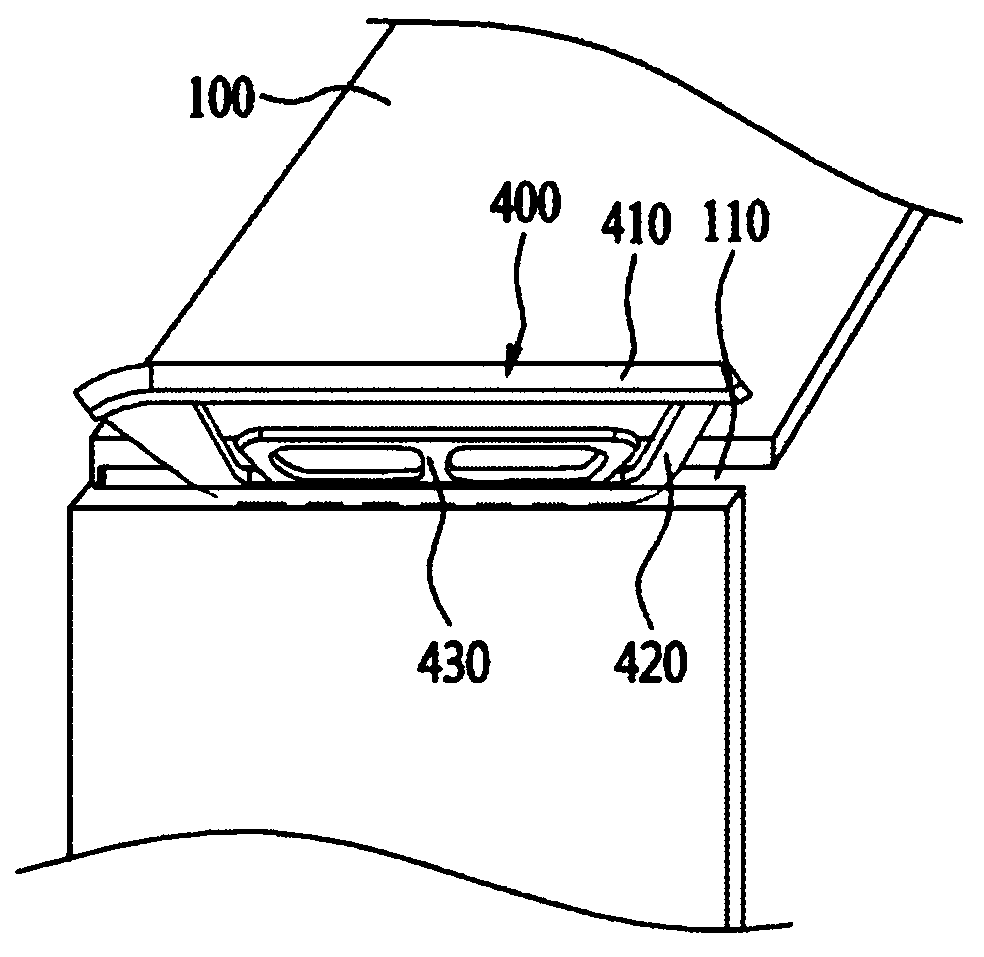
[0049] image 3 is a diagram illustrating a process of inserting an insert assembly 400 according to the present disclosure in a gap region 110 of a panel 100 to trim the insert assembly 400 .

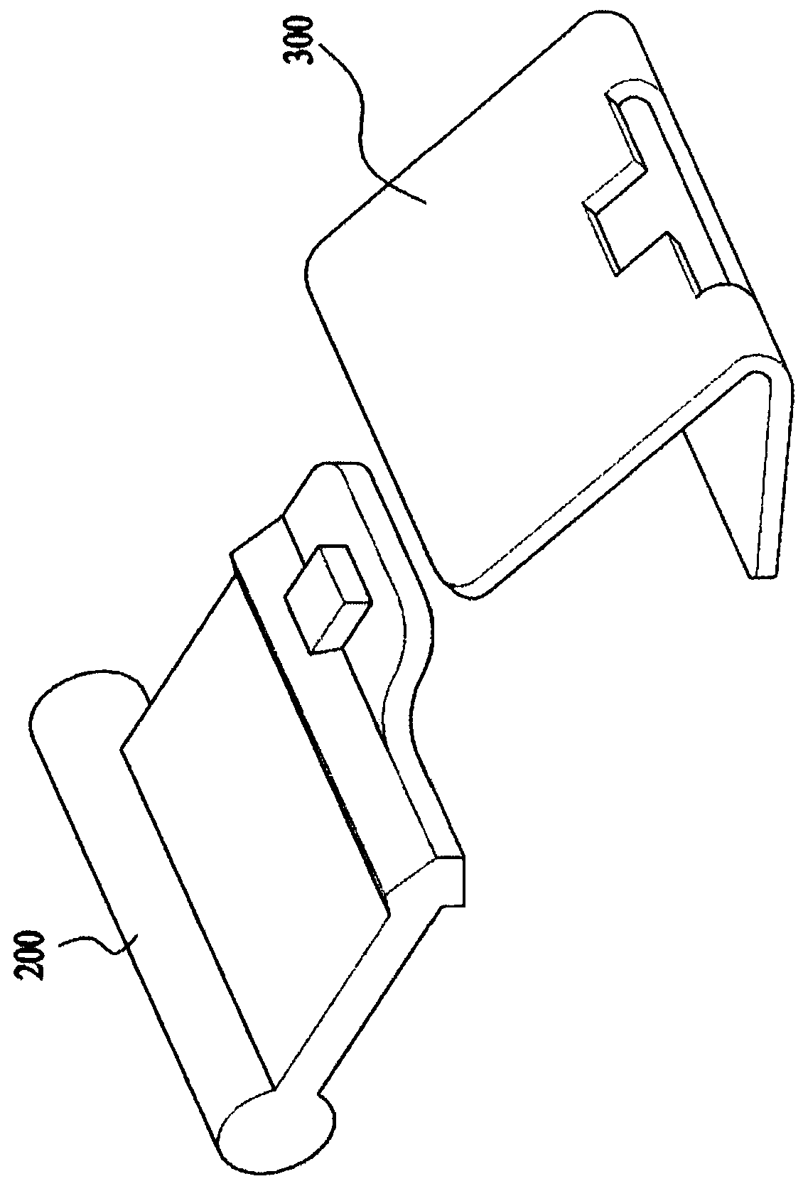
[0050] The insertion assembly 400 includes: a body unit 410, the body unit 410 does not expose a hole or a slit (hereinafter referred to as a gap area) of the cab...


PUM


Abstract

Disclosed is an insertion assembly which is inserted into a gap area provided in a panel to fill the gap area, the insertion assembly including: a body unit covering the gap area so that the gap area is not exposed to the outside; an insertion unit extending from the body unit and inserted into the gap region; and a hook unit extending from the insertion unit to the body unit at a preset distance, the hook unit including one end connected to the insertion unit and set free The other end of the end, wherein the body unit, the insertion unit and the hook unit are integrally formed with each other.

Description

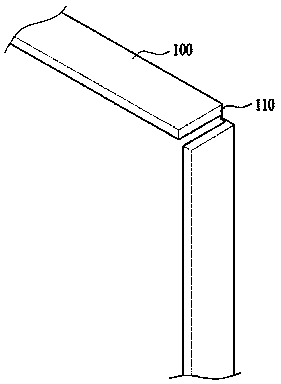
technical field [0001] Embodiments of the present disclosure relate to an insert assembly for trimming a clearance area in order to enhance the appearance and stability of a home appliance having a clearance area such as a hole or a slit. Background technique [0002] refer to figure 1 , the panel 100 used in home appliances is manufactured by bending one side and the other side of a steel plate. [0003] One side and the other side are arranged next to each other during the bending process and then form the corner 100 . [0004] In this case, it is not possible to fully join the two sides during bending, and often slits or holes (hereinafter referred to as gap regions) are formed. [0005] The gap region 110 exposes the sharp surface of the steel plate and degrades safety. In addition, the clearance area 110 produces tolerances or more errors, and thus it is difficult to assemble the parts. [0006] Therefore, according to the prior art to which this disclosure relates,...

Claims


Application Information

Patent Timeline
Patent Type & Authority Patents(China)
IPC IPC(8): H05K5/06
CPCH05K5/06D06F39/12A47B95/002A47L15/427F24C15/08F24C15/30Y10T403/1608A47B2230/01A47B47/0033F16B5/0614
Inventor 郭孝星金玟徹
Owner LG ELECTRONICS INC
Learn More