Die-cutting and discharging device and method for die-cutting and discharging film with inner handle

A die-cutting and film-cutting technology, which is applied in metal processing and other directions, can solve the problems of easily damaged and positioned products, achieve good waste discharge effect, avoid size deviation, avoid glue overflow and pull glue effects

Inactive Publication Date: 2018-05-04
YUANRANG IND SHANGHAI
View PDF6 Cites 0 Cited by
  • Summary
  • Abstract
  • Description
  • Claims
  • Application Information

AI Technical Summary

Problems solved by technology

[0004] The die-cut parts after punching are positioned in the electronic product according to the outer frame of the entire electronic device. In the traditional design, the outer handle is generally used for the die-cut parts pasted with double-sided adhesive tape. Do not tear off the handle, so the handle needs to be bent. When bending, it is easy to damage the positioning product when it is fitted

Method used


Image

  • Die-cutting and discharging device and method for die-cutting and discharging film with inner handle
  • Die-cutting and discharging device and method for die-cutting and discharging film with inner handle
  • Die-cutting and discharging device and method for die-cutting and discharging film with inner handle

Examples


Embodiment Construction

[0041] The present invention will be described in detail below in conjunction with the accompanying drawings and specific embodiments. This embodiment is carried out on the premise of the technical solution of the present invention, and detailed implementation and specific operation process are given, but the protection scope of the present invention is not limited to the following embodiments.

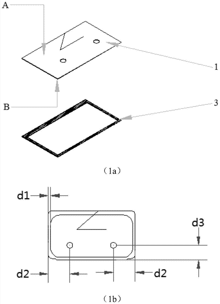
[0042] figure 1 For the design of the double-sided tape for the inner handle, the double-sided tape 3 is attached to the release surface of the first release film 1. The double-sided tape 3 is the size required by the customer, and the first release film 1 is an auxiliary material. Form inner handle and circular hole on a release film 1, as shown in figure (1a), A is the non-release surface of the first release film 1, and B is the release surface of the first release film 1. The inner handle is a sharp corner formed by oblique lines and transverse lines. The angle range of the sharp...


PUM


Abstract

The invention relates to a die-cutting and discharge device for a die-cutting part with an inner lifting handle and a die-cutting and discharge method. The device comprises a first pair of compression rollers, first punching die cutting tools, a second pair of compression mechanisms, second punching die cutting tools, a waste discharge mechanism, a fourth pair of compression rollers, and third punching die cutting tools. The first pair of compression rollers enables a first single-sided glued protection film to be attached on a first release film. The first punching die cutting tools are used for punching diagonal lines. The second pair of compression mechanisms is attached on a double faced adhesive tape and a second release film orderly on the first release film. The second punching die cutting tools are provided with second punching circular holes and inner frames. The waste discharge mechanism is used for discharging waste material of first punching circular holes as well as inner frame waste material of the double faced adhesive tape and the second release film. The fourth pair of compression rollers is attached on a third release film and a second single-sided glued protection film. The third punching die cutting tools are provided with third punching outer frames and used for punching transversely-cut lines. Compared with the prior art, the die-cutting and discharge device for die-cutting parts with inner lifting handles and die-cutting and discharge method have following beneficial effects: the double faced adhesive tape with the inner lifting handle which is subjected to die cutting is advantaged by being easy in die cutting, high in location precision and good in waste discharge effect.

Description

technical field [0001] The invention relates to a die-cutting and discharging device and method, in particular to a die-cutting and discharging device with an inner handle for film cutting. Background technique [0002] Die-cut parts commonly used in the electronics industry include double-sided tape, protective film, cushioning, insulation, shielding, heat conduction, and mesh. It is widely used in the shells, windows, batteries, connectors, circuit boards, backlight modules, camera modules, audio modules and other components of consumer electronics products, and plays a structural or functional reinforcing and auxiliary role. [0003] Due to the rapid update of the electronic market, the die-cut parts are also constantly updated. In order to adapt to the diversified updates of the electronic market, the design of the die-cut parts will also be continuously updated. From the beginning, only the main material of the die-cut parts (customer-specified double-sided tape, foam,...

Claims


Application Information

Patent Timeline
Patent Type & Authority Patents(China)
IPC IPC(8): B26F1/38B26F1/44B26D7/18
Inventor 易小雷邢海周倩
Owner YUANRANG IND SHANGHAI
Why Eureka
Try Eureka