
A shell type capacitor marking printing device

A printing device and capacitor technology, applied in printing, printing presses, screen printing, etc., can solve problems such as affecting production efficiency, low degree of automation, and incorrect marking positions, so as to improve printing work efficiency, save manpower and material resources, good printing effect

Active Publication Date: 2019-04-30
TONGLING QILI ELECTRONICS MATERIALS
View PDF6 Cites 0 Cited by
  • Summary
  • Abstract
  • Description
  • Claims
  • Application Information

AI Technical Summary

Problems solved by technology

[0002] Capacitor is a device that holds charge. Capacitance is one of the electronic components widely used in electronic equipment. It is widely used in DC blocking, coupling, bypass, filtering, tuning loop, energy conversion, control, etc. In the prior art, screen printing is widely used in the logo printing of shell-type capacitors. Manually align the printing frame to the appropriate position of the capacitor and use a scraper to scrape the ink through the screen on the shell-type capacitors. This method There are many deficiencies, the screen cannot be fixed, the shell-type capacitors to be printed are easy to move, and the position of the printed logo is not correct, which often causes rework, wastes manpower and material resources, affects production efficiency, and the degree of automation is not high.

Method used


Image

  • A shell type capacitor marking printing device
  • A shell type capacitor marking printing device

Examples


Embodiment Construction

[0014] In order to make the technical means, creative features, goals and effects of the invention easy to understand, the present invention will be further elaborated below in conjunction with specific illustrations.

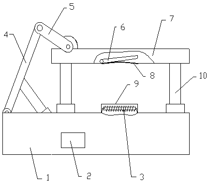
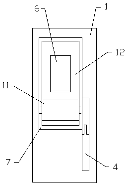
[0015] Such as figure 1 and figure 2 As shown, a shell-type capacitor marking printing device includes a base 1, three electro-hydraulic push rods 10 are arranged on the base 1, two electro-hydraulic push rods 10 are vertically placed, and two vertically placed electro-hydraulic push rods 10 A printing plate 7 is connected above, and a chute 12 is opened in the printing plate 7, and a printing frame 6 and a screen 8 are arranged inside the chute 12, and a scroll wheel 11 is arranged on the chute 12, and one end of the scroll wheel 11 is connected with a first connection Arm 5, the second connecting arm 4 is hinged above the first connecting arm 5, the bottom of the second connecting arm 4 is hinged with the base 1, and the other electro-hydraulic push rod 10 ...


PUM


Abstract

The invention discloses a shell type capacitor identification printing device comprising a base; three electric hydraulic pushing rods are arranged on the base; two of the three electric hydraulic pushing rods are placed vertically; a printing plate is connected on the two electric hydraulic pushing rods placed vertically; a sliding groove is formed in the printing plate; a printing frame and a silk screen are arranged inside the sliding groove; a rolling wheel is arranged in the sliding groove; one end of the rolling wheel is connected with a first connecting arm; the upper portion of the first connecting arm is hinged to a second connecting arm; the lower portion of the second connecting arm is hinged to the base; the another electric hydraulic pushing rod tilts with a certain angle and is fixedly connected with the second connecting arm; a capacitor fixing table is arranged on the base; and an electromagnet is arranged inside the capacitor fixing table. According to the shell type capacitor identification printing device, the positions of the printing frame, the silk screen and a shell type capacitor can be fixed separately; the accuracy of an identification position is improved; additionally, degree of automation is high, manpower and material resources are saved; and production efficiency is improved.

Description

technical field [0001] The invention relates to the technical field of capacitor accessory equipment, and more specifically, to a shell-type capacitor marking printing device. Background technique [0002] Capacitor is a device that holds charge. Capacitance is one of the electronic components widely used in electronic equipment. It is widely used in DC blocking, coupling, bypass, filtering, tuning loop, energy conversion, control, etc. In the prior art, screen printing is widely used in the logo printing of shell-type capacitors. Manually align the printing frame to the appropriate position of the capacitor and use a scraper to scrape the ink through the screen on the shell-type capacitors. This method There are many deficiencies, the screen cannot be fixed, the shell-type capacitors to be printed are easy to move, and the position of the printed logo is not correct, which often causes rework, wastes manpower and material resources, affects production efficiency, and the de...

Claims


Application Information

Patent Timeline
Patent Type & Authority Patents(China)
IPC IPC(8): B41F15/08B41F15/18
CPCB41F15/08B41F15/18B41P2215/50
Inventor 荚朝辉康仙文
Owner TONGLING QILI ELECTRONICS MATERIALS
Learn More