Pressure rack for rebar-planting

A technology of pressure and rebar planting, applied in the direction of drill pipe, casing, drill pipe, etc., to ensure the quality of rebar planting, high safety factor, and avoid electric shock accidents

Inactive Publication Date: 2017-03-29
THE FOURTH ENGIENERING OF CHINA RAILWAY18 BUREAU GROUP +1
View PDF10 Cites 0 Cited by
  • Summary
  • Abstract
  • Description
  • Claims
  • Application Information

AI Technical Summary

Problems solved by technology

[0003] The purpose of the present invention is to overcome the deficiencies in the above-mentioned prior art, and provide a tendon pressure frame, which can not only solve the safety problems such as falling and electric shock and the health problems of pneumoconiosis caused by inhaling dust, but also effectively improve the Rebar construction speed

Method used


Image

  • Pressure rack for rebar-planting

Examples


Embodiment Construction

[0015] The present invention will be further described in detail below in conjunction with the accompanying drawings and specific embodiments.

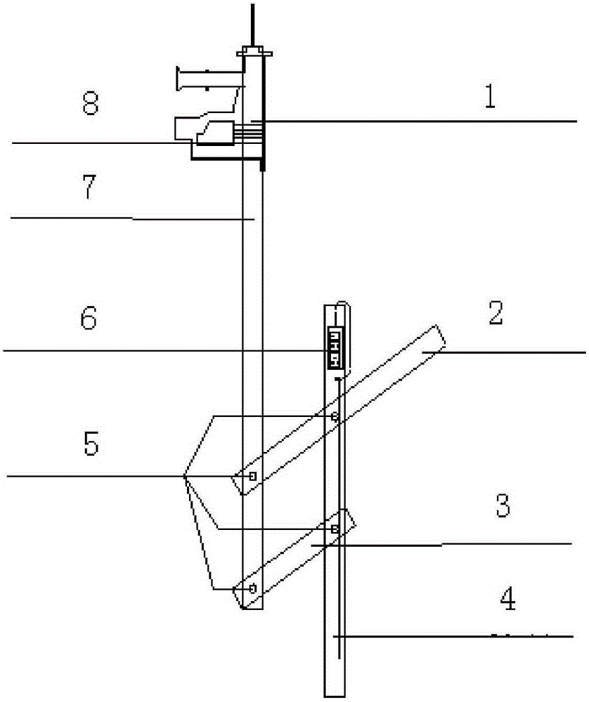
[0016] Such as figure 1 Shown: a pressure frame for planting tendons, composed of 2m longitudinal main stress rod 7, 1.4m support rod 4, 0.4m connecting rod 3 and 1m pressure rod 2. An electric hammer 1 is fixedly installed on the top of the longitudinal main stress rod, and the body of the longitudinal main stress rod is sequentially connected with a pressure rod and a connecting rod through two bolts 5, and the pressure rod and the connecting rod are arranged in parallel. The support rods are respectively connected to the pressure rod and the connecting rod through two bolts 5, and are arranged parallel to the longitudinal main stress rod. Since the connecting rod is 0.4m, which is equivalent to the radius of the rotating shaft being 0.4m, the rising height is 0.8m, so it can meet the needs of general floors. The electric hammer i...


PUM


Abstract

The invention provides a pressure rack for rebar-planting. The rack comprises a main longitudinal stressed rod, a support rod, a connection rod and a pressure rod. The top end of the main longitudinal stressed rod is fixedly equipped with an electric hammer. A rod body of the main longitudinal stressed rod is orderly connected with the pressure rod and the connection rod through bolts. The support rod is connected with the pressure rod and the connection rod through the bolts and parallel to the main longitudinal stressed rod. The pressure rack for rebar-planting has following beneficial effects: the rack is utilized on the ground so that rebar-planting can be achieved without climbing objects; rebar-planting can be finished indoors around floors; and the rack has a high safety coefficient and is convenient to operate and is simple in structure.

Description

technical field [0001] The invention relates to a device for building construction, in particular to a bar planting pressure frame for anchoring longitudinal steel bars of structural columns. Background technique [0002] In urban housing construction projects, there are following defects in using conventional technology to stand on the ladder to anchor the main reinforcement of the structural column and plant the reinforcement: 1. It will cause arm pain or spasm due to holding the electric hammer with one hand for a long time. 2. The dust generated after drilling will enter the eyes and cause dizziness, enter the mouth and respiratory tract and cause coughing, and even long-term inhalation will cause pneumoconiosis. 3. When constructing columns around the floor and adjacent to the opening, it may cause falling accidents and electric shock accidents. 4. Since the beam and slab reinforcement may be drilled during the rebar planting process, the collision between the drill bi...

Claims


Application Information

Patent Timeline
Patent Type & Authority Applications(China)
IPC IPC(8): E21B15/00E21B19/087
Inventor 李宗温淑荔杨宝明李鑫谢泽宇李为为
Owner THE FOURTH ENGIENERING OF CHINA RAILWAY18 BUREAU GROUP
Why Eureka
Try Eureka