Upper clamp assembly and disassembly device with automatic carrying function for dry-type transformer

A technology of dry-type transformers and clamps, which is applied in the field of transformer processing, can solve the problems of low work efficiency, manually pushing the iron core, and long pushing time, and achieve the effect of low labor intensity, preventing excessive movement, and stable transmission

Active Publication Date: 2017-03-29
HENGSHUI POWER SUPPLY BRANCH OF STATE GRID HEBEI ELECTRIC POWER
View PDF6 Cites 10 Cited by
  • Summary
  • Abstract
  • Description
  • Claims
  • Application Information

AI Technical Summary

Problems solved by technology

[0003] In order to solve the above problems, the present invention provides a dry-type transformer upper clip disassembly and assembly equipment with automatic handling function, which can solve the existing manual transformer manufacturing process that requires manual pushing of the iron core, long pushing time, and manual handling. The upper clamping piece, complex operation, high labor intensity and low work efficiency can realize the automatic handling of the transformer core and the automatic disassembly and assembly of the upper clamping piece, without manual operation, with automatic handling of the iron core, short handling time, and automatic removal Put on the clamp, easy to operate, low labor intensity and high work efficiency, etc.

Method used


Image

  • Upper clamp assembly and disassembly device with automatic carrying function for dry-type transformer
  • Upper clamp assembly and disassembly device with automatic carrying function for dry-type transformer
  • Upper clamp assembly and disassembly device with automatic carrying function for dry-type transformer

Examples


Embodiment Construction

[0028] In order to make the technical means, creative features, goals and effects achieved by the present invention easy to understand, the present invention will be further described below in conjunction with specific illustrations.

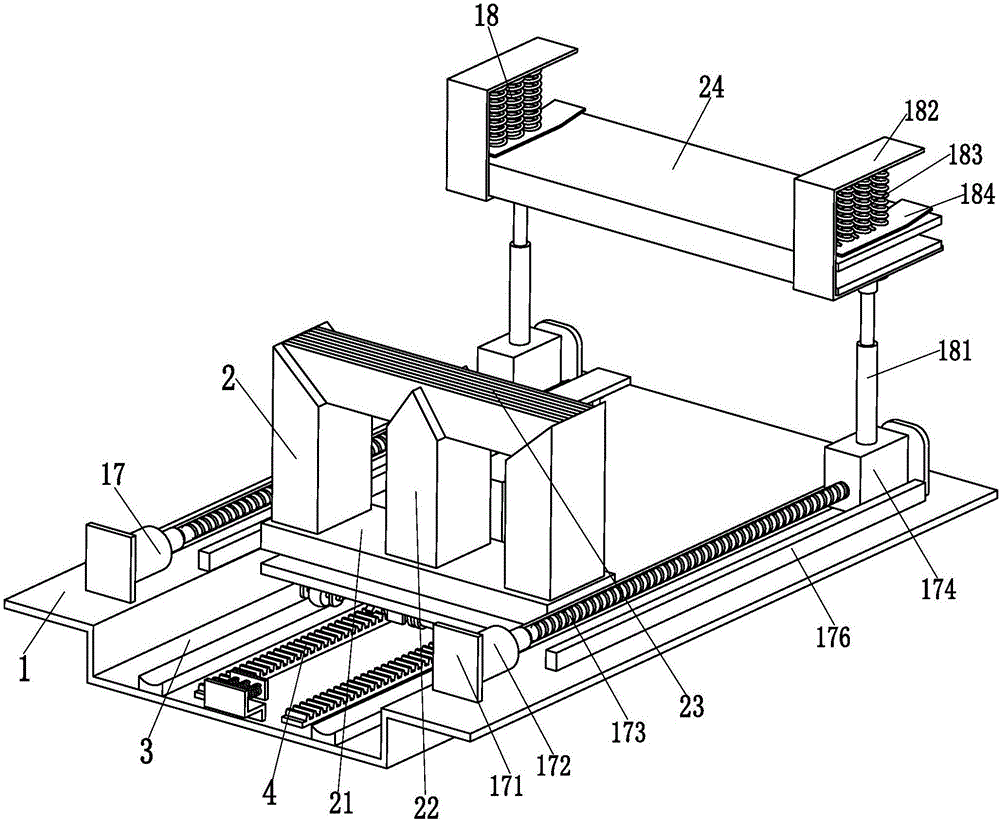
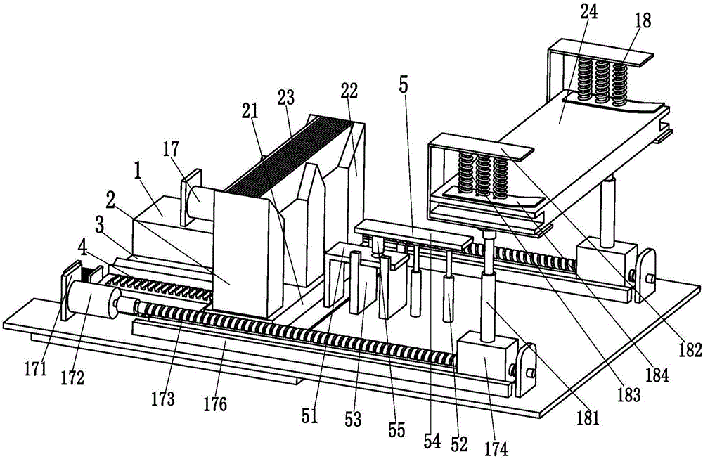
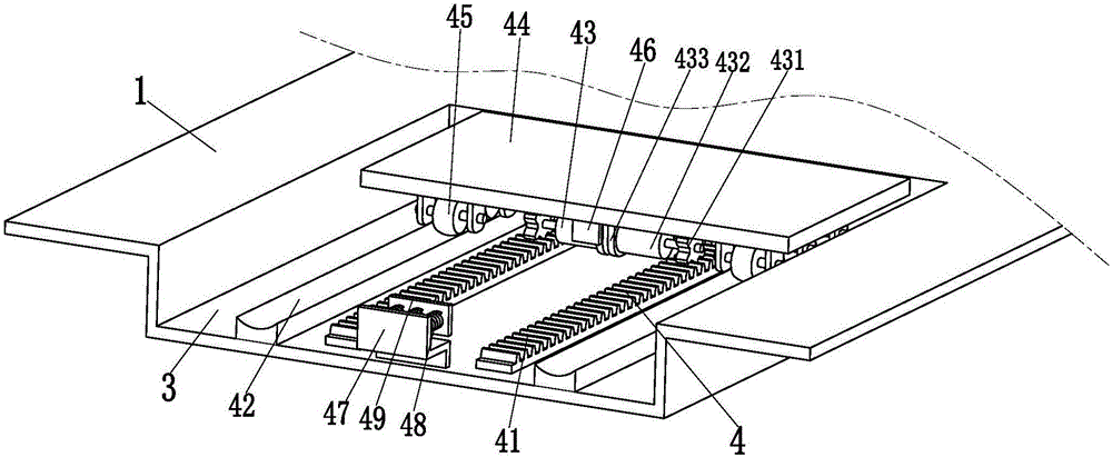
[0029] like Figure 1 to Figure 6 As shown, a dry-type transformer upper clip disassembly and assembly device with automatic handling function includes a base plate 1 and an iron core 2. The type of the iron core 2 is a three-phase three-column iron core in the present invention, and the iron core 2 It consists of a lower iron 21, three core columns 22 evenly installed on the lower iron 21, an upper iron 22 placed on the three cores 22, and an upper clamp 23 installed on the upper iron. The upper iron is composed of several The upper end of the bottom plate 1 is provided with a downwardly concave installation groove 3 on the front side, the upper end surface of the installation groove 3 is equipped with a sliding transport mechanism 4, and the u...


PUM


Abstract

The invention relates to an upper clamp assembly and disassembly device with an automatic carrying function for a dry-type transformer. The upper clamp assembly and disassembly device comprises a bottom plate and an iron core, wherein a concave installation groove is arranged in the front side of the upper end surface of the bottom plate; a sliding carrying mechanism is arranged on the upper end surface of the installation groove; the iron core is put on the upper end of the sliding carrying mechanism and a limiting mechanism is arranged in the middle of the bottom plate; after the sliding carrying mechanism automatically carries the iron core to a specified position, the iron core is locked through the limiting mechanism, so that the iron core does not move when the transformer is manufactured, and the condition that the iron core moves to affect the manufacturing efficiency of the transformer is avoided; two power mechanisms are symmetrically arranged at the left side and the right side of the upper end surface of the bottom plate; each power mechanism is provided with a clamping branch chain for clamping an upper clamp; and the two clamping branch chains are driven to move back and forth through the two power mechanisms. According to the upper clamp assembly and disassembly device, automatic carrying of the iron core of the transformer and the automatic assembly and disassembly function on the upper clamp can be achieved and manual operation is not needed.

Description

technical field [0001] The invention relates to the technical field of transformer processing, in particular to a device for disassembling and assembling clamps on dry-type transformers with an automatic handling function. Background technique [0002] The transformer uses the principle of electromagnetic induction to change the AC voltage. It has the functions of voltage conversion, current conversion, impedance conversion, isolation and voltage stabilization. Therefore, it is widely used in distribution network substations. The transformer is composed of a coil and an iron core. The core is mainly composed of the lower clamp, the lower iron, the core column, the upper iron and the upper clamp. The manufacturing process of the transformer is as follows: the first step is to transport the iron core to the required location by forklift or roadway, and then Manually push the iron core to the designated installation position for easy installation; the second step is to manually...

Claims


Application Information

Patent Timeline
Patent Type & Authority Applications(China)
IPC IPC(8): H01F41/00B65G47/74
CPCB65G47/74H01F41/00
Inventor 储德姣
Owner HENGSHUI POWER SUPPLY BRANCH OF STATE GRID HEBEI ELECTRIC POWER
Why Eureka
Try Eureka