
Mobile charge control method and control system for to-be-charged electric vehicle

A technology for electric vehicles and mobile charging, applied in electric vehicles, charging stations, vehicle energy storage, etc., can solve the problems of increased load, increased mileage, and high cost, and achieve the effect of long-term battery life

Active Publication Date: 2017-03-29
深圳北斗应用技术研究院有限公司
View PDF6 Cites 30 Cited by
  • Summary
  • Abstract
  • Description
  • Claims
  • Application Information

AI Technical Summary

Problems solved by technology

[0003] The conventional solution is to increase the cruising range and build a large number of charging stations, but both methods have their own shortcomings
The cruising range of an electric vehicle is mainly related to its loaded battery pack. The larger the capacity of the battery pack, the more energy it can provide. Theoretically, the cruising range can be increased, but the battery pack with a larger capacity also makes the load of the electric vehicle In fact, the mileage cannot be increased linearly; on the other hand, many factors such as manpower and material resources need to be considered in the construction of a large number of charging stations, especially in today's big cities where land resources are already quite scarce, the cost of construction may be even higher. high

Method used


Image

  • Mobile charge control method and control system for to-be-charged electric vehicle
  • Mobile charge control method and control system for to-be-charged electric vehicle
  • Mobile charge control method and control system for to-be-charged electric vehicle

Examples


Embodiment Construction

[0040] In order to make the object, technical solution and advantages of the present invention clearer, the present invention will be further described in detail below in conjunction with the accompanying drawings and embodiments. It should be understood that the specific embodiments described here are only used to explain the present invention, not to limit the present invention.

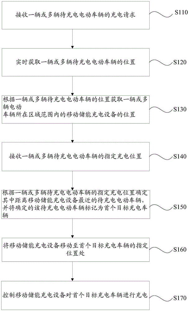
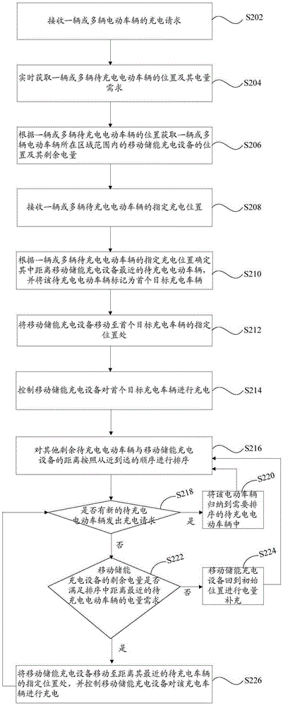
[0041] figure 1 It is a flowchart of a mobile charging control method for an electric vehicle to be charged in an embodiment, including the following steps:

[0042] S110. Receive charging requests from one or more electric vehicles to be charged.

[0043] One or more users who need to charge the electric vehicles can send a charging request through the smart terminal. Specifically, the smart terminal may be a mobile phone, a tablet, a vehicle-mounted computer, or other smart electronic devices installed with corresponding application program management software.

[0044] S120, obtaining the pos...


PUM


Abstract

The invention relates to a mobile charge control method for an electric vehicle. The mobile charge control method comprises the following steps of receiving charging requests from one or more to-be-charged electric vehicles; obtaining positions and appointed charging positions of the one or more to-be-charged electric vehicles in real time; obtaining position of mobile energy storage charging equipment in the regional range of the to-be-charged electric vehicles; and determining the to-be-charged electric vehicle which is nearest to the mobile energy storage charging equipment, and enabling the to-be-charged electric vehicle to be moved to the nearest charging vehicle appointed position to be charged. By adoption of the mobile charge control method for the electric vehicle, the corresponding to-be-charged electric vehicles can be charged in time, so that a battery pack load is not required to be added on the electric vehicle while long-time endurance can be realized; and a charging station with high cost is not required to be established. The invention also provides a mobile charge control system for the electric vehicle applying the control method.

Description

technical field [0001] The invention relates to the technical field of electric vehicle charging, in particular to a mobile charging control method and control system for an electric vehicle to be charged. Background technique [0002] With the increasing air pollution and energy shortage, electric vehicles (EV) are getting more and more attention. Compared with traditional fuel vehicles, electric vehicles have huge advantages in reducing exhaust emissions and energy consumption. There are currently two main factors restricting the development of electric vehicles: the short range of electric vehicles and the lack of charging facilities, both of which are also the reasons for "Range Anxiety". [0003] The conventional solution is to increase the cruising range and build a large number of charging stations, but both methods have their own defects. The cruising range of an electric vehicle is mainly related to its loaded battery pack. The larger the capacity of the battery pa...

Claims


Application Information

Patent Timeline
IPC IPC(8): H02J7/00B60L11/18
CPCB60L53/00B60L53/36B60L53/65H02J7/00H02J7/0048Y02T10/70Y02T10/7072Y02T90/12Y02T90/14Y02T90/16
Inventor 田智勇张帆张瑞张鋆
Owner 深圳北斗应用技术研究院有限公司
Learn More