Machine leg welding equipment for compressor and use method of machine leg welding equipment

A compressor and machine foot technology, used in welding equipment, auxiliary welding equipment, welding/cutting auxiliary equipment, etc., can solve the problems of welding position deviation, reduce production accuracy, reduce production efficiency, etc., to reduce assembly errors, improve The effect of production efficiency, quick alignment and quick disassembly

Active Publication Date: 2017-04-05
杭州瀚真电器制造有限公司
View PDF5 Cites 3 Cited by
  • Summary
  • Abstract
  • Description
  • Claims
  • Application Information

AI Technical Summary

Problems solved by technology

[0002] The surface of the casing of the compressor is a curved surface, and the machine feet must be installed on both sides of the casing. The two casing feet need to be clamped and welded repeatedly. , it is easy to produce errors, resulting in deviations in welding positions and reducing production accuracy
Moreover, repeated clamping and multiple welding waste time, reduce production efficiency, and cause large errors in manual positioning

Method used


Image

  • Machine leg welding equipment for compressor and use method of machine leg welding equipment
  • Machine leg welding equipment for compressor and use method of machine leg welding equipment
  • Machine leg welding equipment for compressor and use method of machine leg welding equipment

Examples


Embodiment 1

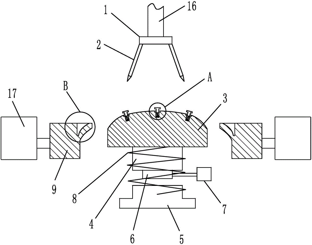
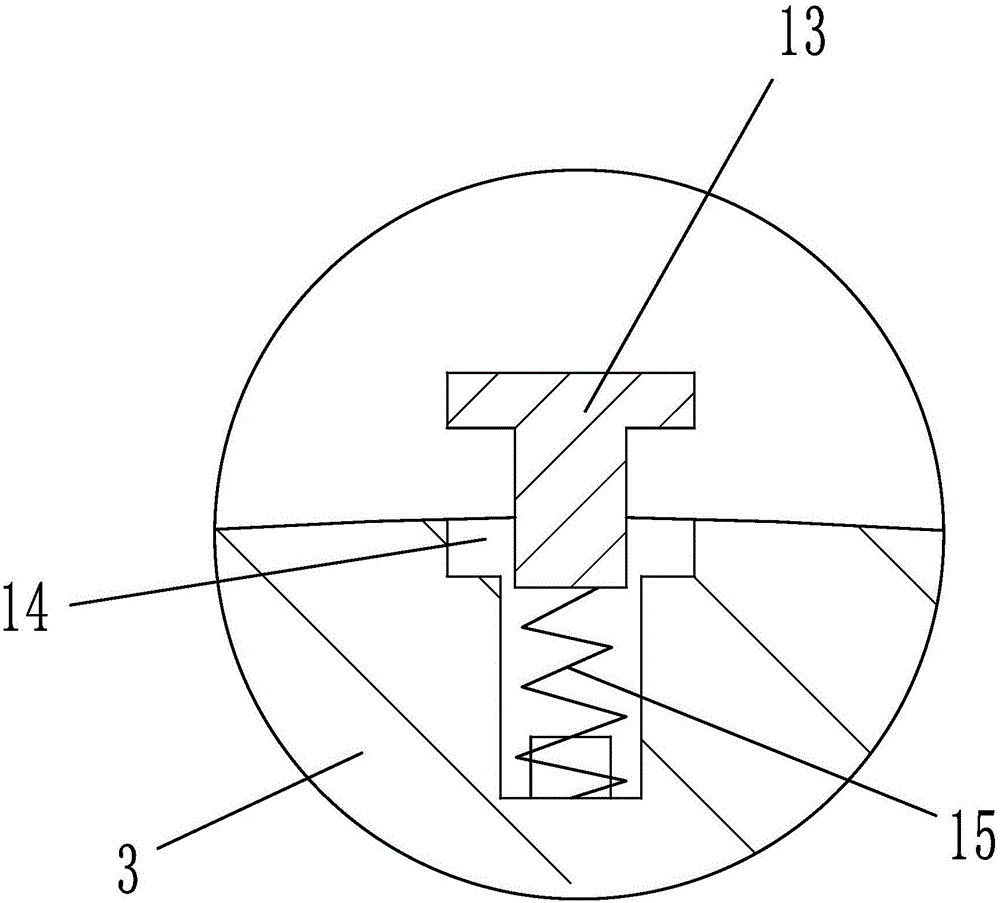
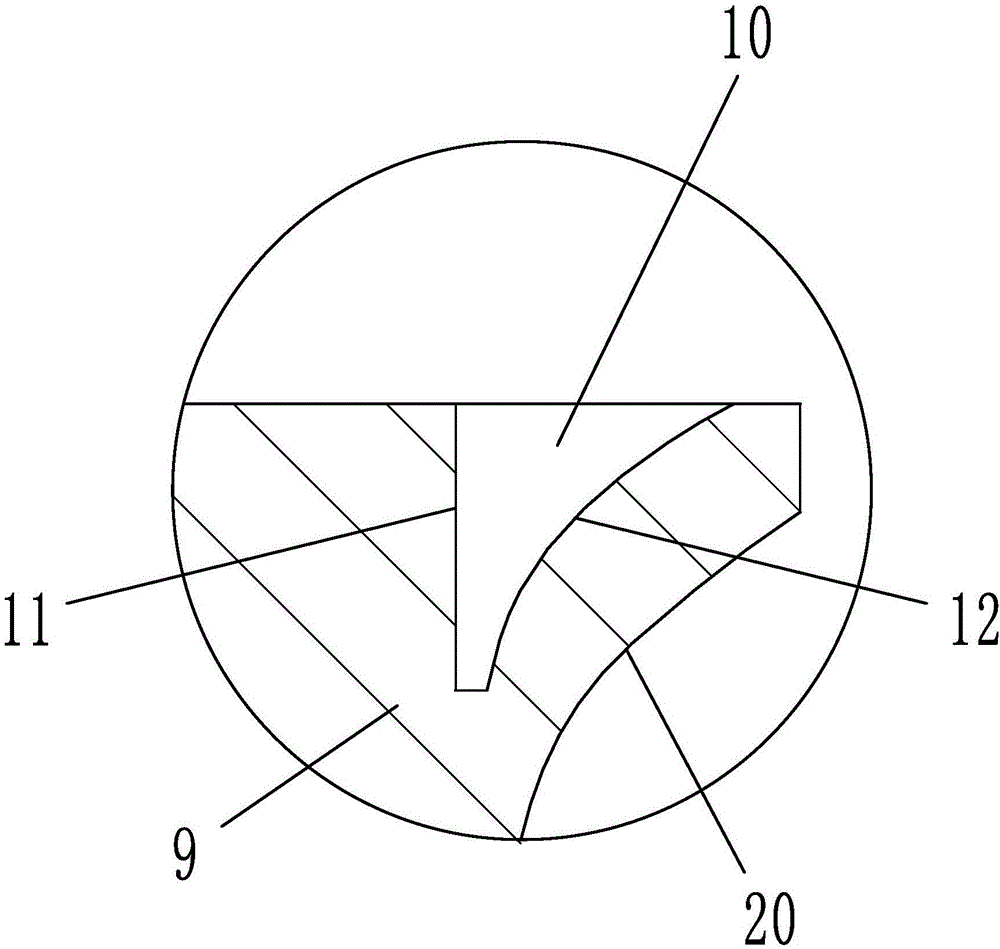
[0018] Embodiment 1: as figure 1 , 2, 3, and 4, a compressor foot welding equipment, including positioning head 3 cooperating with the inner surface of the casing 18, claws 9 positioned on both sides of the positioning head and a welding mechanism positioned above the positioning head, the positioning head A column 4 is arranged on the axis of the lower end surface, a positioning column 5 is arranged coaxially below the column, a positioning spring 8 is set on the outside of the column and the positioning column, a vibration column 6 is arranged at the bottom of the column, and a vibrator 7 is connected to the vibration column; A guide surface 20 matching the shape of the outer surface of the positioning head is provided on the end surface close to the positioning head, and a positioning groove 10 for fixing the machine foot 19 is provided on the edge of the upper end surface of the claw close to the positioning head, and the positioning groove is far from the end of the posit...

Embodiment 2

[0021] Embodiment 2: The structure of this embodiment is basically the same as that of Embodiment 1, the difference is that, as Image 6 , 7 As shown, the positioning head includes a left half head 31 and a right half head 32, and the middle part of the left half head and the right half head is provided with a positioning hole 26, and the positioning hole is provided with a positioning shaft 27 that cooperates with the positioning hole clearance. Position straight face 28 and sliding arc surface 29, the section of positioning hole is " D " font. The positioning head includes a left half head and a right half head. There are positioning holes in the middle of the left half head and the right half head. The positioning shaft is arranged in the positioning hole to fit with the positioning hole. The left half head and the right half head can be positioned through The shaft changes the distance between the two, which in turn changes the length of the positioning head, so that the ...


PUM


Abstract

The invention relates to processing of compressor parts, in particular to machine leg welding equipment for a compressor and a use method of the machine leg welding equipment. The machine leg welding equipment for the compressor comprises a positioning head matched with the inner surface of a case, jack catches positioned on two sides of the positioning head and a welding mechanism positioned above the positioning head, wherein a guiding face matched with the shape of the outer surface of the positioning head is formed on the end surface of the end, close to the positioning head, of each jack catch, and the end, far away from the positioning head, of each jack catch is connected with a driving cylinder; the welding mechanism comprises a positioning base and welding guns positioned on the positioning base, and an adjustment cylinder used for controlling the positioning base to ascend or descend is arranged on the positioning base; and T-shaped adjustment heads are uniformly distributed on the outer surface of the positioning head, adjustment holes for accommodating the adjustment heads are formed in the outer surface of the positioning head, and adjustment springs are arranged between the adjustment holes and the adjustment heads. The machine leg welding equipment has the beneficial effects that the clamping frequency can be effectively reduced, the positioning precision can be effectively improved, the welding frequency can be effectively reduced, multi-point simultaneous welding is effectively realized and the production efficiency is effectively improved.

Description

technical field [0001] The invention relates to a processing of compressor parts, in particular to a compressor foot welding equipment and a method for using the same. Background technique [0002] The surface of the casing of the compressor is a curved surface, and the machine feet must be installed on both sides of the casing. The two casing feet need to be clamped and welded repeatedly. , It is easy to produce errors, resulting in deviations in welding positions and reducing production accuracy. Moreover, repeated clamping and multiple welding waste time, reduce production efficiency, and cause large errors in manual positioning. Contents of the invention [0003] The present invention mainly aims at the above problems, and provides a compressor foot welding equipment and its use method which can effectively reduce the number of clamping times, increase the positioning accuracy, reduce the number of welding times, realize multi-point simultaneous welding, and improve p...

Claims


Application Information

Patent Timeline
Patent Type & Authority Applications(China)
IPC IPC(8): B23K37/04B23K37/02
CPCB23K37/02B23K37/04B23K37/0443
Inventor 张友奎钱治魁
Owner 杭州瀚真电器制造有限公司
Why Eureka
Try Eureka