A portable detachable and installable new energy vehicle charging pile

A technology of new energy vehicles and charging piles, applied in electric vehicle charging technology, charging stations, electric vehicles, etc., can solve the problems of high disassembly and assembly efficiency, low labor cost, and low disassembly and assembly efficiency, and achieve high work efficiency and drill The effect of high hole efficiency and high disassembly efficiency

Active Publication Date: 2018-10-16
深圳市夏瑞科技股份有限公司
View PDF7 Cites 0 Cited by
  • Summary
  • Abstract
  • Description
  • Claims
  • Application Information

AI Technical Summary

Problems solved by technology

[0004] In order to solve the above problems, the present invention provides a new energy vehicle charging pile that can be portable, disassembled and installed, which can solve the problems of existing fixed installation methods of charging piles that require many disassembly and assembly personnel, complicated operations, high labor costs, and high labor intensity. , slow disassembly and assembly process, low disassembly and assembly efficiency, and low work efficiency, etc., can realize the movable installation and automatic disassembly function of the charging pile, without manual disassembly and assembly, easy operation, high work efficiency, and only one person to operate, labor The advantages of low cost, low labor intensity, fast disassembly and assembly process and high disassembly and assembly efficiency

Method used


Image

  • A portable detachable and installable new energy vehicle charging pile
  • A portable detachable and installable new energy vehicle charging pile
  • A portable detachable and installable new energy vehicle charging pile

Examples


Embodiment Construction

[0027] In order to make it easy to understand the technical means, creative features, objectives and effects achieved by the present invention, the present invention will be further explained below in conjunction with specific drawings.

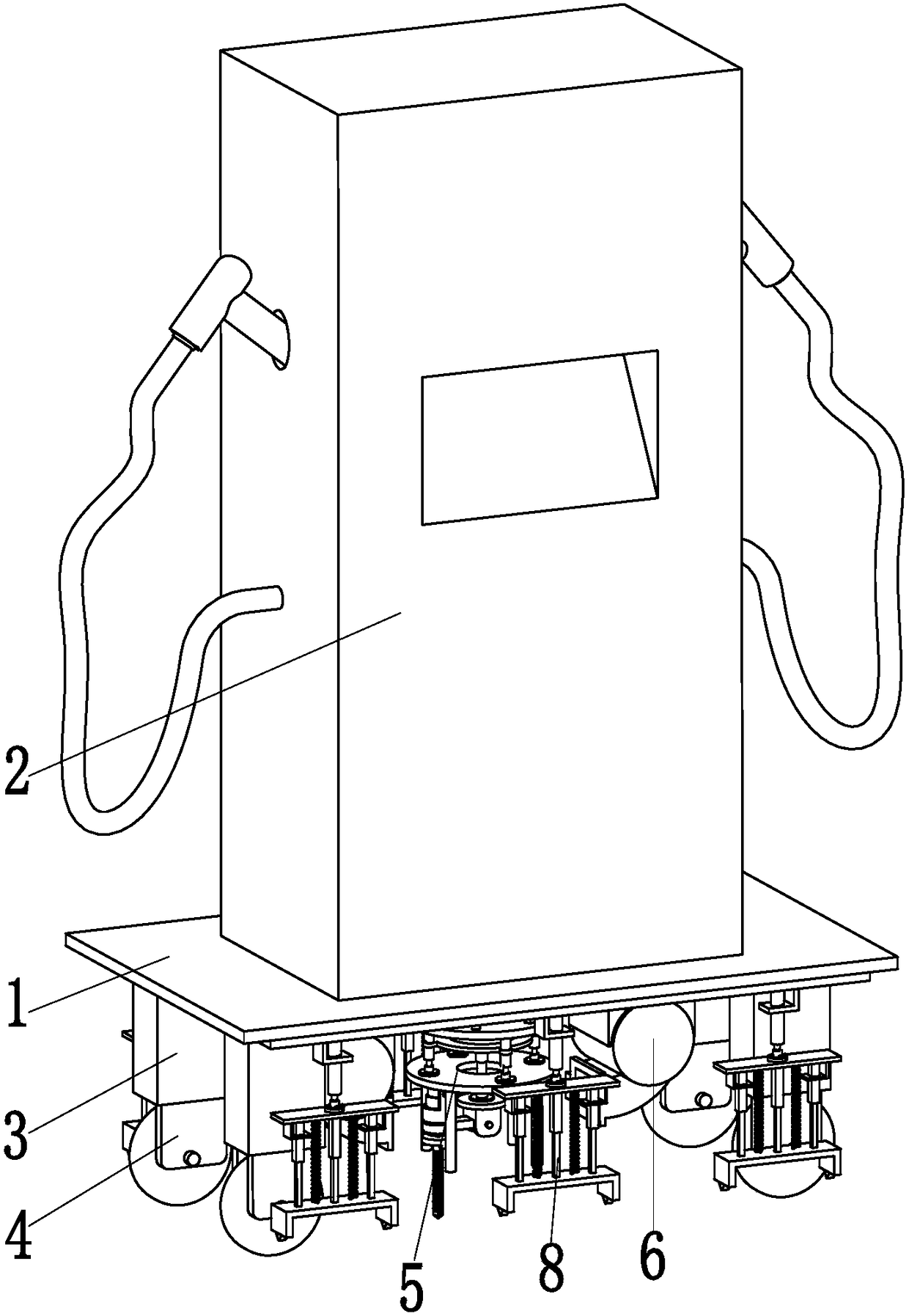
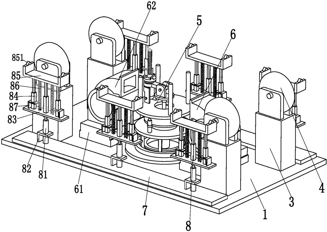
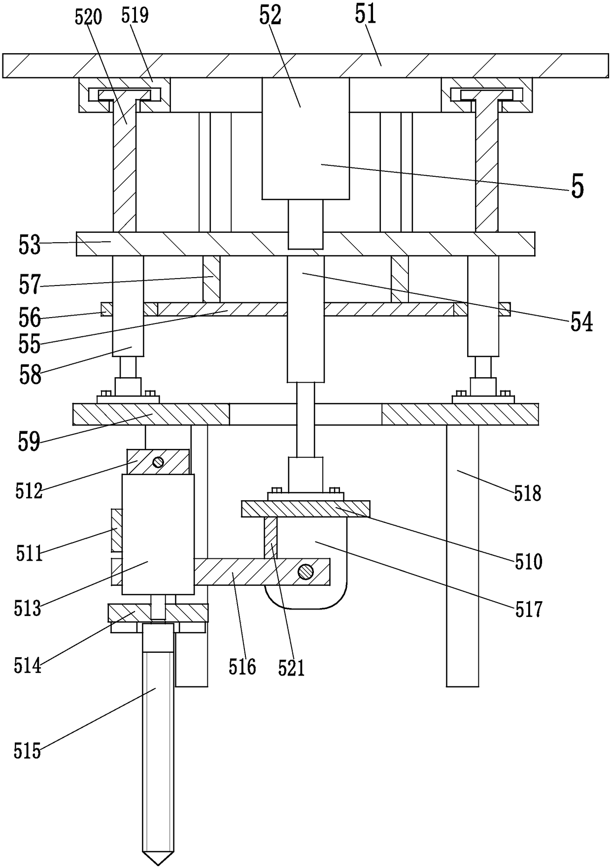
[0028] Such as Figure 1 to Figure 4 As shown, a portable, detachable and installable new energy vehicle charging pile includes a bottom plate 1, a pile body 2 is placed on the upper end of the bottom plate 1, and four mounting posts 3 are symmetrically installed on the lower end of the bottom plate 1, each The bottom ends of the mounting posts 3 are all equipped with omnidirectional wheels 4, and the present invention is moved to the required installation position through the four omnidirectional wheels 4 on the four mounting posts 3; the middle of the lower end surface of the bottom plate 1 is equipped with a disassembly and assembly mechanism 5. The disassembly and assembly mechanism 5 can realize the movable installation and automatic disass...


PUM


Abstract

The invention relates to a charging pile capable of being portably dismounted and mounted for a new energy automobile. The charging pile comprises a base plate, wherein a pile body is arranged on the upper end face of the base plate; four mounting columns are symmetrically arranged on the lower end face of the base plate; an omnidirectional wheel is arranged at the bottom end of each mounting column; a dismounting / mounting mechanism is arranged at the middle part of the lower end face of the base plate, can realize the functions of movably mounting and automatically dismounting the pile body, and does not need manual mounting; two dust collecting mechanisms are symmetrically arranged on the left side and the right side of the end face of the base plate and are positioned on two sides of the dismounting mechanism in an opposite manner; two mounting plates are symmetrically arranged on the front side and the rear side of the lower end face of the base plate; and three motion preventing supporting mechanisms are transversely and uniformly arranged on the lower end face of each mounting plate. According to the charging pile disclosed by the invention, the functions of movably mounting and automatically dismounting the pile body can be realized, and manual dismounting and mounting is not needed, so the simplicity and the convenience in operation are realized, and the working efficiency is high; and in addition, the charging pile has the advantages of operation by only one person, low labor cost, low labor intensity, quick dismounting and mounting process, high dismounting and mounting efficiency and the like.

Description

Technical field [0001] The invention relates to the technical field of charging piles, in particular to a new energy vehicle charging pile that can be detachably installed. Background technique [0002] Charging piles can charge various types of electric vehicles according to different voltage levels. Charging piles can charge time, electricity, and money, and can be used as citizens' electricity purchase terminals. It is mainly fixed on the ground or wall and installed in public buildings, shopping malls, public parking lots, office buildings, government buildings and other public buildings or parking lots in residential communities. The input end of the charging pile is directly connected to the AC grid, and the output end is equipped with a charging plug for charging electric vehicles. [0003] Since the existing charging pile manufacturers and the charging pile placement company have signed a contract, when the contract expires, the charging pile needs to be removed and shippe...

Claims


Application Information

Patent Timeline
Patent Type & Authority Patents(China)
IPC IPC(8): B60L11/18B62B5/04
CPCB60L53/30B60L53/31B62B5/049Y02T10/70Y02T10/7072Y02T90/12
Inventor 冒鹏飞
Owner 深圳市夏瑞科技股份有限公司
Why Eureka
Try Eureka