Roll unloading device and roll unloading method for winding equipment

A kind of equipment and technology of rewinding shaft, applied in the direction of winding strip, transportation and packaging, thin material processing, etc., can solve the problems of long time consumption, high labor intensity of workers, low degree of automation, etc., to reduce labor intensity and save unloading. Rolling process, the effect of high degree of automation

Active Publication Date: 2017-12-22
GUANGDONG JINMING MACHINERY
View PDF8 Cites 0 Cited by
  • Summary
  • Abstract
  • Description
  • Claims
  • Application Information

AI Technical Summary

Problems solved by technology

[0004] The traditional coil unloading and core loading process is mainly carried out manually, with low degree of automation, high labor intensity and long time-consuming

Method used


Image

  • Roll unloading device and roll unloading method for winding equipment
  • Roll unloading device and roll unloading method for winding equipment
  • Roll unloading device and roll unloading method for winding equipment

Examples


Embodiment 1

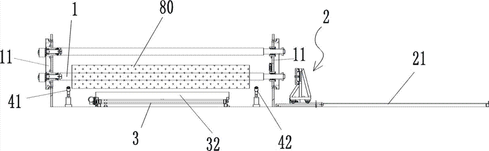
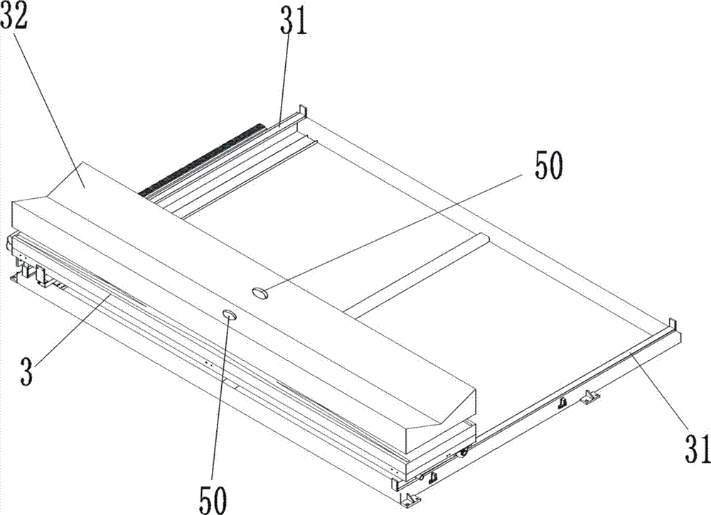
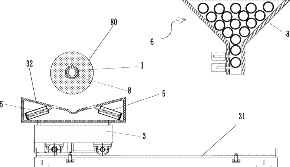
[0062] figure 1 , figure 2 , image 3 , Figure 4 , Figure 5 As shown, the unwinding device of the rewinding device includes an inflatable rewinding shaft 1, the central axis of the rewinding shaft extends laterally, and the left and right ends of the rewinding shaft 1 are installed on the rewinding shaft supports 11 on both sides, and the rewinding shaft supports 11 It is a turntable type rewinding shaft support, and two rewinding shafts can be installed to take turns to rewind and unload; among them, the rewinding shaft support 11 located on the left side is equipped with a rotatable plug 12, and the central axis of the plug 12 rotates with the rewinding shaft 1 The central axis of the winding shaft overlaps, and a plug driving mechanism that drives the plug to rotate is also provided on the left side of the winding shaft bracket 11; the left end of the winding shaft 1 forms a movable plugging relationship with the plug 12, and the plugging direction is The axial direc...

Embodiment 2

[0069] A method for automatically unloading a core, adopting the automatic unloading device of the winding equipment of Embodiment 1, comprising the following steps in sequence:

[0070] (1), figure 1 , figure 2 , image 3 , Figure 4 , Figure 5 As shown, when preparing to unload, the rewinding shaft 1 is at the unloading position (in figure 1 , figure 2 , Figure 6 , Figure 7 , Figure 15 , Figure 18 , Figure 19 , Figure 21 , Figure 26 Among them, there are two upper and lower rewinding shafts, among which the unloading state is the lower one); the paper core tube 8 is set outside the rewinding shaft, and the rewinding shaft 1 is in the state of inflation and expansion, and is closely combined with the paper core tube 8 Together, the film roll 80 is wound outside the paper core tube 8, the left end of the winding shaft 1 is inserted into the plug 12, the spline 141 of the plug 12 is inserted into the keyway 142 at the left end of the winding shaft 1, and t...


PUM


Abstract

An unwinding device of a rewinding device, comprising an inflatable rewinding shaft, the right end of which is sheathed with a bearing, and an annular groove is formed on the outer surface of the outer ring of the bearing. A card strip can be rotatably installed, and an annular flange is also formed at the rightmost end of the rewinding shaft. A horizontal guide rail extending horizontally is also provided on the right side of the right rewinding shaft support. The core trolley, the left side of the core pulling trolley is equipped with two clamping blocks matched in pairs; there is also a longitudinally extending longitudinal guide rail under the winding shaft, and a carrying trolley capable of carrying film rolls is installed on the longitudinal guide rail. Just below the left end of the winding shaft is provided with a left supporting shaft roller that can support the winding shaft, and a right supporting shaft roller that can support the winding shaft is also provided directly below the right end of the winding shaft. The invention also provides a coil unloading method of the coiling device. The invention can automatically complete the coil unloading process, and has a high degree of automation.

Description

technical field [0001] The invention belongs to the technical field of winding in the film production process, and in particular relates to a winding device and a winding unloading method. Background technique [0002] After the film is produced, it needs to be wound around the paper core tube by the winding equipment to become a coil. The outer diameter of the commonly used paper core tube is 96-110mm. During the winding process, the paper core tube is set outside the rewinding shaft, and the paper core tube is driven by the rewinding shaft to rotate continuously, so that the film material is continuously wound up. When the winding reaches the set length and the film roll reaches the set diameter, it is necessary to extract the film roll (together with the paper core) from the winding shaft and transport the film roll to the designated position. This process is called "unloading". After the unloading is completed, a new spare paper core needs to be put on the winding shaf...

Claims


Application Information

Patent Timeline
Patent Type & Authority Patents(China)
IPC IPC(8): B65H19/30B65H75/24
CPCB65H19/30B65H75/242B65H2701/1752B65H75/243B65H2405/312B65H2405/4221B65H2301/41814B65H2301/41822B65H2301/418526B65H2301/41366B65H2408/23152
Inventor 陈俊鸿陈昭楷付龙莉
Owner GUANGDONG JINMING MACHINERY
Why Eureka
Try Eureka