Air cylinder shell and air cylinder shell tool clamp

A technology for tooling fixtures and shells, which is applied in the direction of manufacturing tools, clamping, positioning devices, etc., can solve problems such as flattening of cylinder shells, easy inward depression of the outer wall, affecting product quality, etc.

Inactive Publication Date: 2017-04-05
SUZHOU ENVIL MACHINERY
View PDF9 Cites 4 Cited by
  • Summary
  • Abstract
  • Description
  • Claims
  • Application Information

AI Technical Summary

Problems solved by technology

When processing the end face of a part, the outer wall of the part is usually clamped, and the part is fixed by the clamping force. You can refer to some existing fixtures, such as the patent with application number 201520005643.5, and this is done by applying pressure to the outer wall of the part. The fixed way makes the outer wall easy to sag inward
Especially for thin-walled parts like cy

Method used


Image

  • Air cylinder shell and air cylinder shell tool clamp
  • Air cylinder shell and air cylinder shell tool clamp
  • Air cylinder shell and air cylinder shell tool clamp

Examples


Example Embodiment

[0027] The embodiments of the present invention will be further described with reference to the accompanying drawings.

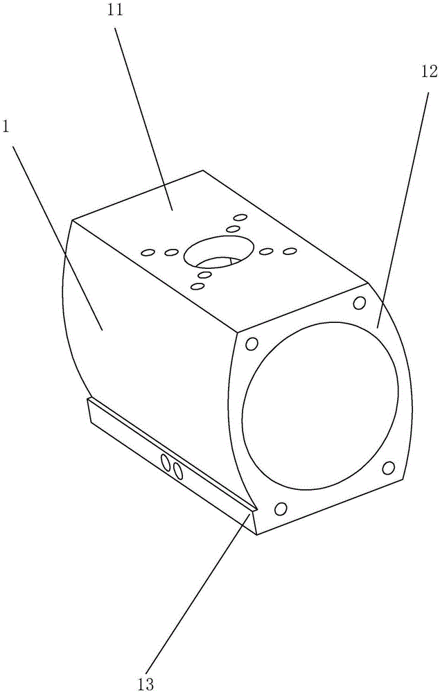
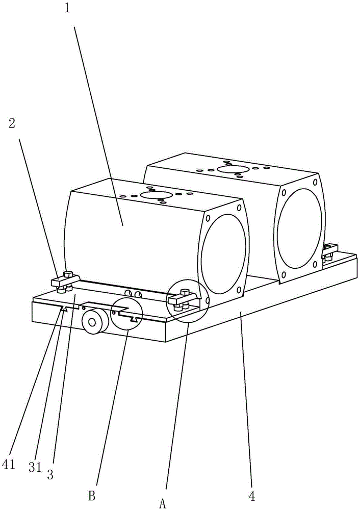
[0028] A cylinder housing includes a casing 1, the casing 1 includes four sides and two end faces 12, two opposite sides are formed with a placement plane 11, and the other two opposite sides are formed as arc surfaces, and the arc faces extend outward A clamping step 13 is formed. The clamping step 13 is close to the placement plane 11. The clamping step 13 is used for clamping the tooling fixture when the end face 12 is processed. After the tooling fixture clamps the clamping step 13, it is mainly the clamping step 13. The force is applied during processing, which can prevent the tooling fixture from being clamped on the surface of the cylinder casing, thereby avoiding the flattening of the cylinder casing.

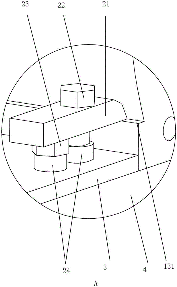
[0029] For more stable clamping of the cylinder shell, the clamping step 13 includes a clamping surface 131 and a positioning surface. The positionin...


PUM

PropertyMeasurementUnit
Widthaaaaaaaaaa

Abstract

The invention discloses an air cylinder shell. According to the technical scheme, the air cylinder shell comprises a shell body, the shell body comprises four side faces and two end faces, two opposite side faces form a containing plane, the other two opposite side faces form a circular-arc face, the circular-arc face extends outwards to form a clamping step, the clamping step is close to the containing plane, and the aims that clamping is convenient, and during clamping, flattening is avoided are achieved; according to the technical scheme, an air cylinder shell tool clamp comprises a base used for containing the air cylinder shell, a clamping assembly used for clamping parts is arranged on the base, the clamping assembly comprises a clamping jaw matched with the clamping step on the air cylinder shell and a driving part used for driving the clamping jaw and the clamping face of the clamping step to be in abut joint, and the aim that when a thin-wall part is clamped, deformation is not prone to happening is achieved.

Description

technical field [0001] The invention relates to a part and a fixture for the part, more specifically, it relates to a cylinder shell and a tooling fixture for the cylinder shell. Background technique [0002] When machining parts, in order to fix the parts firmly on the machining center or lathe, usually or use a tooling fixture that cooperates with the machining center or lathe. When processing the end face of a part, the outer wall of the part is usually clamped, and the part is fixed by the clamping force. You can refer to some existing fixtures, such as the patent with application number 201520005643.5, and this is done by applying pressure to the outer wall of the part. The fixed way makes the outer wall easy to sag inward. Especially for thin-walled parts like cylinder shells, clamps are usually used to press the two planes of the cylinder shell up and down, so as to fix the cylinder shell, and process the end face of the cylinder shell. The material of the cylinder s...

Claims


Application Information

Patent Timeline
IPC IPC(8): F16M1/026B23Q3/06
Inventor 王雪峰
Owner SUZHOU ENVIL MACHINERY
Why Eureka
Try Eureka