A frequency isolation method and device

A frequency and isolation value technology, applied in the field of frequency isolation methods and devices, can solve the problems of reduced effectiveness and no setting principle, and achieve the effect of ensuring system performance and simplifying the network planning process

Active Publication Date: 2020-07-03
CHINA MOBILE COMM GRP CO LTD
View PDF7 Cites 0 Cited by
  • Summary
  • Abstract
  • Description
  • Claims
  • Application Information

AI Technical Summary

Problems solved by technology

However, in the prior art, the selection of the frequency isolation cell in the existing network and the setting of the size of the frequency isolation mainly depend on simulation or engineering experience. In complex scenarios, the effectiveness of existing setting methods will be further reduced

Method used


Image

  • A frequency isolation method and device
  • A frequency isolation method and device
  • A frequency isolation method and device

Examples


Embodiment 1

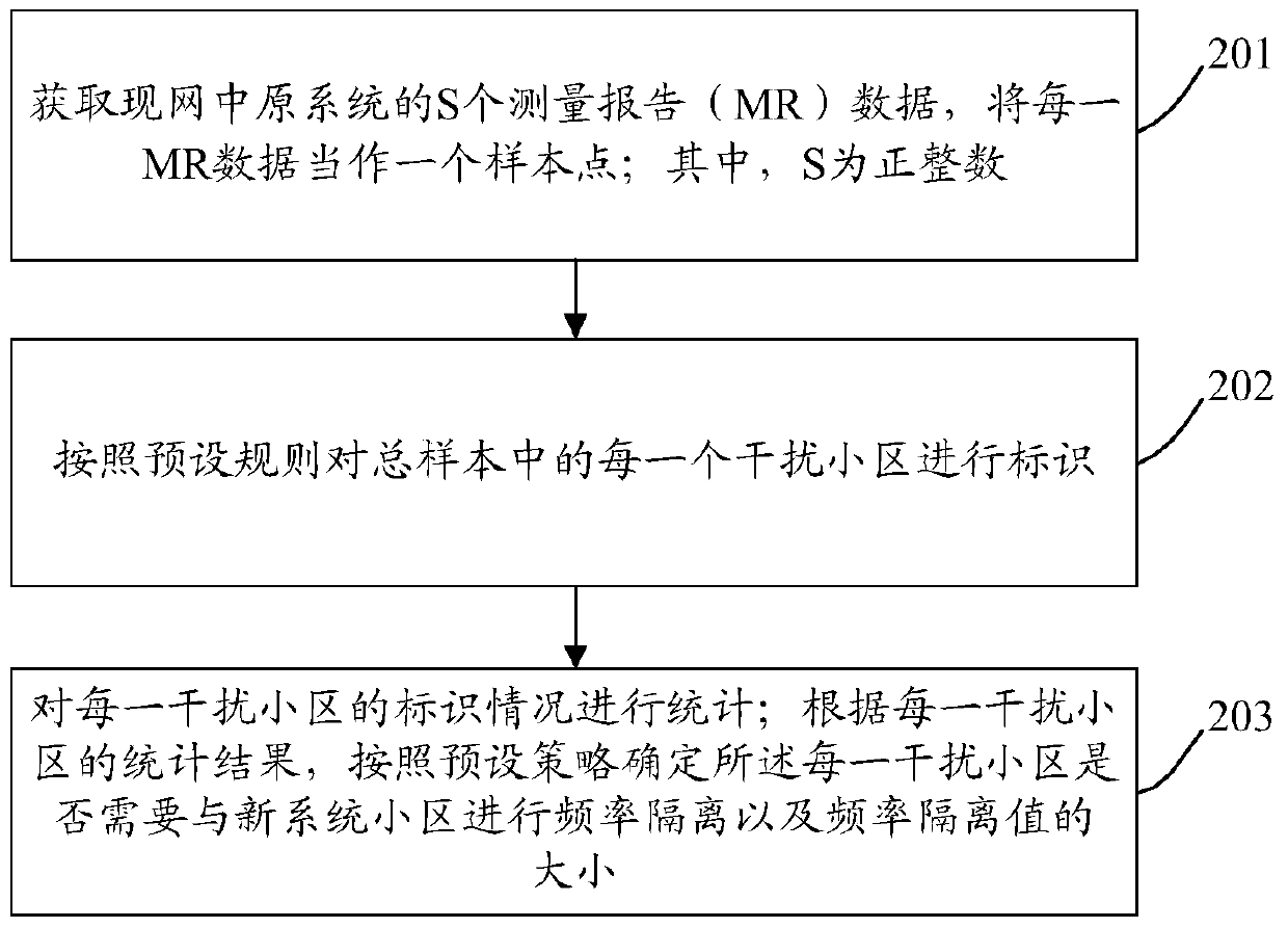
[0034] figure 2 Implementation process of the frequency isolation method provided by the present invention Figure 1 ,Such as figure 2 As shown, the method mainly includes the following steps:

[0035] Step 201: Obtain S pieces of MR data of the central origin system of the existing network, and regard each MR data as a sample point; wherein, S is a positive integer.

[0036] Specifically, the MR data may be collected through a network management system or a drive test system.

[0037] Wherein, each piece of MR data contains multiple interfering cells; different pieces of MR data include the same number or different numbers of interfering cells; different pieces of MR data may include the same interfering cells, or may include different cells . For example, the first MR data contains interfering cell 1 to interfering cell 6; the second MR data contains interfering cell 3 to interfering cell 8; the third MR data contains interfering cell 5 to interfering cell 10 .

[00...

Embodiment 2

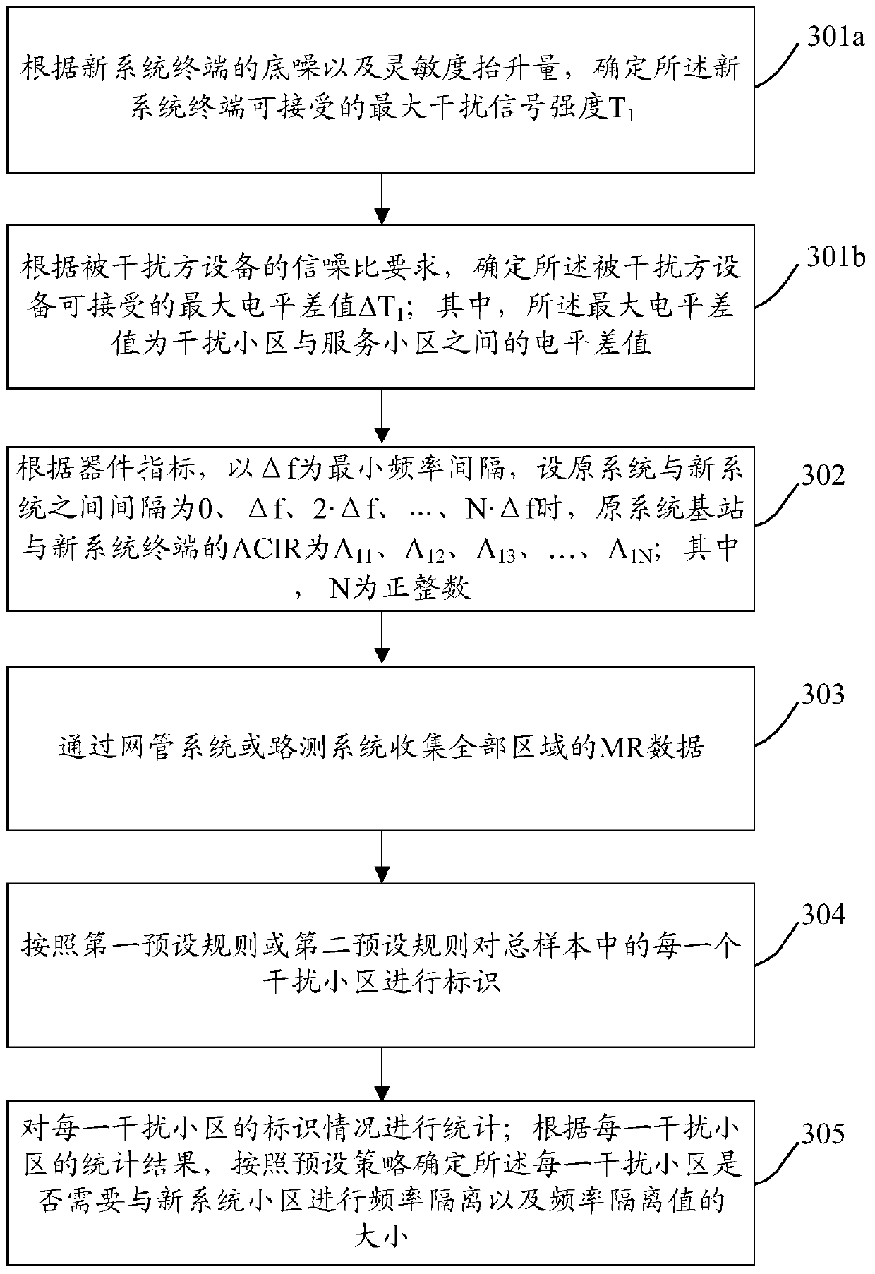
[0106] image 3 Implementation process of the frequency isolation method provided by the present invention Figure II ,Such as image 3 As shown, the method mainly includes the following steps:

[0107] Step 301a: Determine the maximum acceptable interference signal strength T for the new system terminal according to the noise floor and the sensitivity increase of the new system terminal 1 .

[0108] Step 301b: Determine the maximum level difference ΔT acceptable to the interfered device according to the signal-to-noise ratio requirement of the interfered device 1 ; Wherein, the maximum level difference is the level difference between the interfering cell and the serving cell.

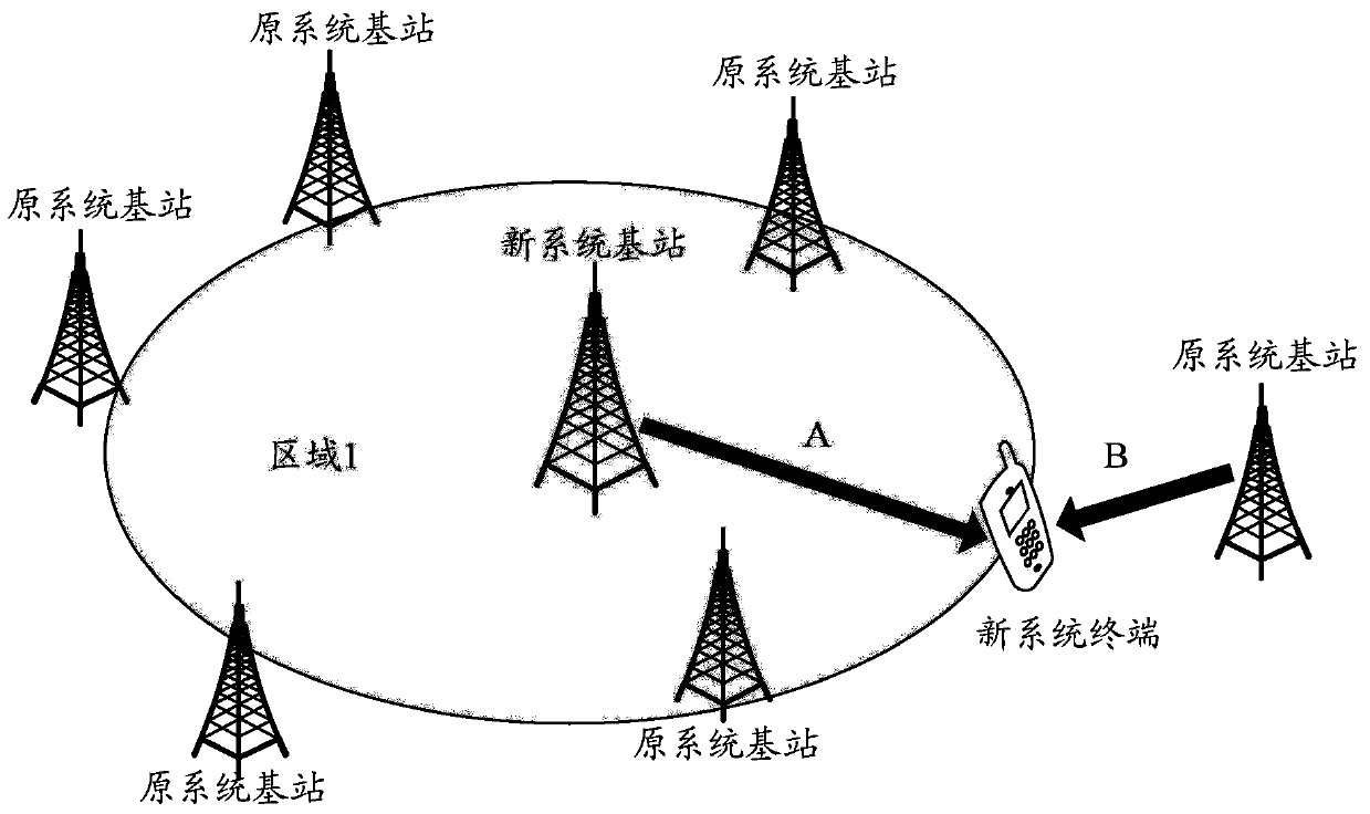
[0109] Figure 4 It shows the interference diagram of the original system base station to the new system terminal provided by the present invention. If the frequencies are close to each other, when the new system terminal is at the edge of the coverage of the new system cell, and the original syst...

Embodiment 3

[0154] Figure 5 Implementation process of the frequency isolation method provided by the present invention Figure three ,Such as Figure 5 As shown, the method mainly includes the following steps:

[0155] Step 501: Determine the maximum acceptable interference signal strength T for the new system terminal according to the noise floor and the sensitivity increase of the new system terminal 2 .

[0156] Figure 6 It shows the interference diagram of the original system terminal to the new system base station provided by the present invention. When the original system terminal is at the coverage edge of the original system cell and the original system terminal interferes strongly with the adjacent frequency of the new system cell, the original system needs to have a connection with the new system. Frequency isolation, and the greater the interference, the greater the frequency isolation.

[0157] Step 502: According to the device index, with Δf as the minimum frequency in...


PUM


Abstract

The invention discloses a frequency isolation method comprising: obtaining the data of S measurement reports (MR) of the original system of the current grid; and using the data of each MR as a sampling point wherein S is a positive integer; according to preset rules, carrying out identification to each interfering cell in the total samples; making statistics on the identification condition of each interfering cell; and based on the statistical result of each interfering cell and according to the preset strategy, determining whether each interfering cell needs to be subjected to frequency isolation from a new system cell or not and the frequency isolation value. The invention also discloses a frequency isolation apparatus. With the technical schemes of the invention, it is possible to clearly indicate the choice of a frequency isolation cell and the configuration of the frequency isolation magnitude, simplify the configured network planning procedure and effectively ensure the performances of two systems.

Description

technical field [0001] The invention relates to frequency isolation technology in the field of wireless communication, in particular to a frequency isolation method and device. Background technique [0002] With the development of wireless communication technologies, more and more operators upgrade and utilize frequency resources originally occupied by systems with lower spectral efficiency (that is, frequency refarming), and apply these frequency resources to standards with higher spectral efficiency. In the process of frequency refarming, because the original system is still in use, only part of the frequency can be used for the new system. When part of the frequency of the original system is refarmed to the new system, the original system and the new system may occupy adjacent frequencies, so Frequency isolation needs to be established. [0003] In general, due to the out-of-band attenuation of the transmitting and receiving filters, the impact of adjacent channel interf...

Claims


Application Information

Patent Timeline
Patent Type & Authority Patents(China)
IPC IPC(8): H04W16/14H04W16/18
CPCH04W16/14H04W16/18
Inventor 李新何文林邵华诸葛毅蔡玮王玮林兴吴晶
Owner CHINA MOBILE COMM GRP CO LTD
Why Eureka
Try Eureka