Hydraulic mount and its assembly, control method, control unit, ecu and automobile

A control unit and hydraulic mount technology, which are applied in the fields of control methods, control units, ECUs and automobiles, hydraulic mounts and their assemblies, and can solve problems such as the inability of hydraulic mounts to adjust stiffness in real time.

Active Publication Date: 2018-11-20
SAIC MOTOR
View PDF7 Cites 0 Cited by
  • Summary
  • Abstract
  • Description
  • Claims
  • Application Information

AI Technical Summary

Problems solved by technology

[0007] The problem solved by the invention is that the hydraulic mount cannot adjust the stiffness in real time

Method used


Image

  • Hydraulic mount and its assembly, control method, control unit, ecu and automobile
  • Hydraulic mount and its assembly, control method, control unit, ecu and automobile
  • Hydraulic mount and its assembly, control method, control unit, ecu and automobile

Examples


Embodiment 1

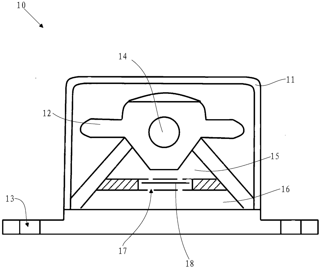
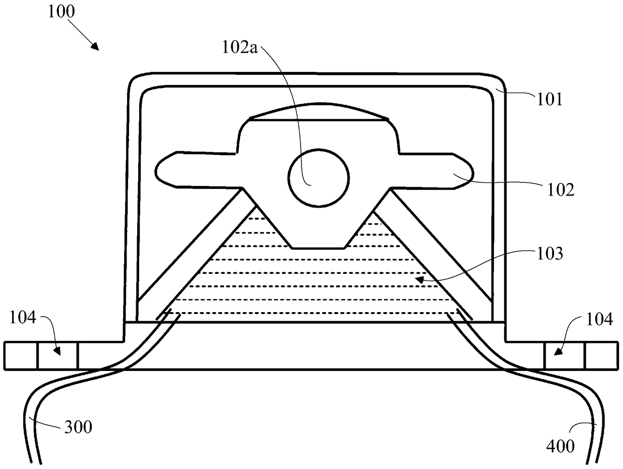
[0077] refer to figure 2 The embodiment of the present invention provides a hydraulic mount 100, comprising: a housing 101 having an inner cavity, the housing 101 is made of metal, and the hydraulic mount 100 further includes: a rubber main spring 102 located in the inner cavity; The rubber main spring 102 and the bottom wall of the housing 101 form a hydraulic chamber 103, which is filled with liquid, which is ethylene glycol in this embodiment; the rubber main spring 102 is provided with a mounting bracket 102a for use with The engine (not shown in the figure) is connected, and the casing 101 is used to connect with the automobile body, specifically: the casing 101 is provided with a bolt hole 104, and the casing 101 is installed on the automobile body by installing a bolt in the bolt hole 104. On the vehicle body, in this embodiment, the housing 101 is installed on the longitudinal beam of the vehicle body.

[0078] The hydraulic chamber 103 communicates with the outside ...

Embodiment 2

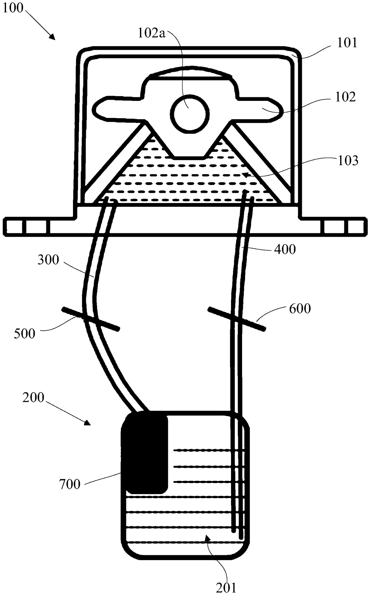
[0082] A hydraulic mount assembly is provided in this embodiment, refer to image 3 and combine figure 2 As shown, it includes a hydraulic mount 100 and a liquid storage bottle 200, the inner chamber 201 of the liquid storage bottle 200 is also filled with liquid, and the liquid storage bottle 200 communicates with the hydraulic chamber 103 in the hydraulic mount 100 through pipe fittings; in this embodiment , the pipe fittings include a first pipe fitting 300 and a second pipe fitting 400, the first pipe fitting 300 is provided with a first valve 500, and the second pipe fitting 400 is provided with a second valve 600, in this embodiment, the first valve 500 and the second valve 600 are solenoid valves; oil inlet and outlet are provided on hydraulic chamber 103, and oil inlet and outlet are also provided on liquid storage bottle 200, thus, the oil inlet and liquid storage on hydraulic chamber 103 The oil inlet on the bottle 200 communicates through the first pipe 300 ; the ...

Embodiment 3

[0087] In this embodiment, the flow of liquid between the hydraulic chamber 103 and the liquid storage bottle 200 is controlled by the first valve 500, the second valve 600 and the pumping device 700, and the pumping device 700 is a pump in this embodiment; The opening or closing of the first valve 500, the second valve 600 and the pump is controlled by the suspension assembly control unit, refer to Figure 4 , when the suspension assembly control unit determines that the stiffness of the hydraulic mount 100 needs to be increased, the suspension assembly control unit sends a first instruction, the first instruction is: send an opening instruction to the first valve 500 and the pump, and send an opening instruction to the second valve 500. The valve 600 sends a closing command; then, the first valve 500 is opened, the pump works, the second valve 600 is closed, and the liquid flows from the liquid storage bottle 200 to the hydraulic chamber 103 through the first pipe 300 .

[0...


PUM


Abstract

The invention discloses a hydraulic mount, a hydraulic mount assembly, a control method, a control unit, an ECU and an automobile. The hydraulic mount comprises a casing with an inner cavity and a rubber main spring positioned in the inner cavity, wherein the rubber main spring is used for being connected with an engine; the casing is used for being connected with an automobile body; the rubber main spring and the bottom wall of the casing define a hydraulic chamber; the hydraulic chamber is filled with liquid and communicates with the outside through an opening in the chamber wall; the liquid can flow to the outside through the opening; and external liquid can flow towards the hydraulic chamber through the opening. When the rigidity of the hydraulic mount needs to be reduced, the liquid can flow to the outside through the opening in the chamber wall, and the rigidity of the hydraulic mount is reduced; and when the rigidity of the hydraulic mount needs to be increased, the liquid flows to the hydraulic chamber through the opening in the chamber wall, the rigidity of the hydraulic mount is increased, and the adjustment of the rigidity of the hydraulic mount can be realized.

Description

technical field [0001] The invention relates to the technical field of automobiles, in particular to a hydraulic mount and its assembly, a control method, a control unit, an ECU and an automobile. Background technique [0002] At present, vehicles are more and more commonly integrated into the lives of ordinary families. People are also paying more and more attention to the performance indicators of cars. Among them, the low noise of the vehicle has become a very important index of vehicle comfort. As is well known, the engine is a very important source of vibration for a vehicle. In order to reduce the impact of engine vibration on the comfort of the car, an engine mount is set between the engine and the body, and the engine is connected to the body through the engine mount. The vibration of the engine is transmitted to the frame or body through the suspension. Therefore, minimizing the vibration and noise transmission of the engine is the key to improving the ride comfo...

Claims


Application Information

Patent Timeline
Patent Type & Authority Patents(China)
IPC IPC(8): F16F13/06B60K5/12
Inventor 康飞梁映珍严纬华辛兢泽陶侃饶志明童荣辉王琪李憬刘永李丽
Owner SAIC MOTOR
Why Eureka
Try Eureka