A real-time adjustment method for the stiffness of the probe of an atomic force microscope

An atomic force microscope and real-time adjustment technology, applied in scanning probe technology, scanning probe microscopy, instruments, etc., can solve problems such as narrow application range, complex structure, and cantilever beam failure, so as to reduce probe loss and work The effect of a wide range and a large adjustment range

Active Publication Date: 2021-10-19
JIANGSU JICUI MICRO NANO AUTOMATION SYST & EQUIP TECH RES INST CO LTD
View PDF28 Cites 0 Cited by
  • Summary
  • Abstract
  • Description
  • Claims
  • Application Information

AI Technical Summary

Problems solved by technology

However, due to the tensile stress inside the cantilever beam, it is easy to cause the cantilever beam to fail during the nano-indentation process.
[0008] In summary, manual replacement of the atomic force microscope probe is time-consuming and laborious, and the probe is easy to be damaged during the replacement process; while changing the stiffness of the probe in real time currently requires high technical requirements, and the working range of the probe in the vertical direction is low, and the cantilever Technical problems such as easy failure of beams, narrow scope of application, complex structure

Method used


Image

  • A real-time adjustment method for the stiffness of the probe of an atomic force microscope
  • A real-time adjustment method for the stiffness of the probe of an atomic force microscope
  • A real-time adjustment method for the stiffness of the probe of an atomic force microscope

Examples


Embodiment 1

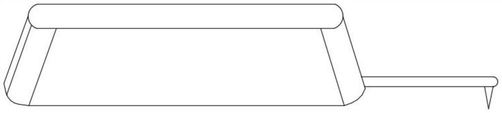
[0041] refer to figure 1 As shown, the invention discloses a real-time adjustment method for the stiffness of a probe of an atomic force microscope, comprising the following steps:

[0042] S1. A cantilever beam is coated with a stiffness adjustment layer to form a cantilever beam-coating composite. The stiffness adjustment layer is a metal layer, and the melting point of the metal layer is lower than that of the cantilever beam.

[0043] The metal layer is an alloy composed of one or more of indium, bismuth, tin and gold.

[0044] The stiffness adjustment layer is prepared by methods such as coating method, electron beam sputtering method, chemical vapor deposition method or focused ion beam deposition method.

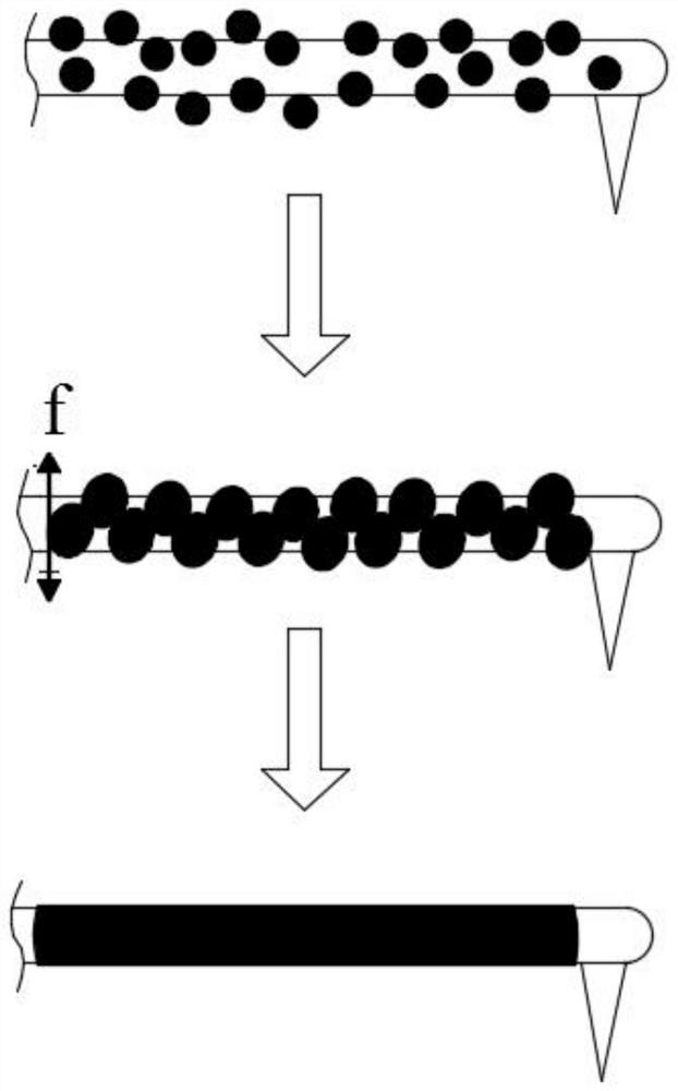
[0045] S2. Change the stiffness of the cantilever beam-coating composite by changing the temperature of the stiffness adjustment layer, specifically including:

[0046] S21, heating the probe, melting the metal layer on the cantilever beam, and obtaining molten met...

Embodiment 2

[0061] The invention discloses a method for adjusting the stiffness of a probe of an atomic force microscope in real time, comprising the following steps:

[0062] S1. A cantilever beam is coated with a stiffness adjustment layer to form a cantilever beam-coating composite. The stiffness adjustment layer is a metal layer, and the melting point of the metal layer is lower than that of the cantilever beam.

[0063] The metal layer is an alloy composed of one or more of indium, bismuth, tin and gold.

[0064] The stiffness adjustment layer is prepared by methods such as coating method, electron beam sputtering method, chemical vapor deposition method or focused ion beam deposition method.

[0065] S2. Change the stiffness of the cantilever beam-coating composite by changing the temperature of the stiffness adjustment layer, specifically including:

[0066] S21, heating the probe, melting the metal layer on the cantilever beam, and obtaining molten metal in a molten state;

[0...

Embodiment 3

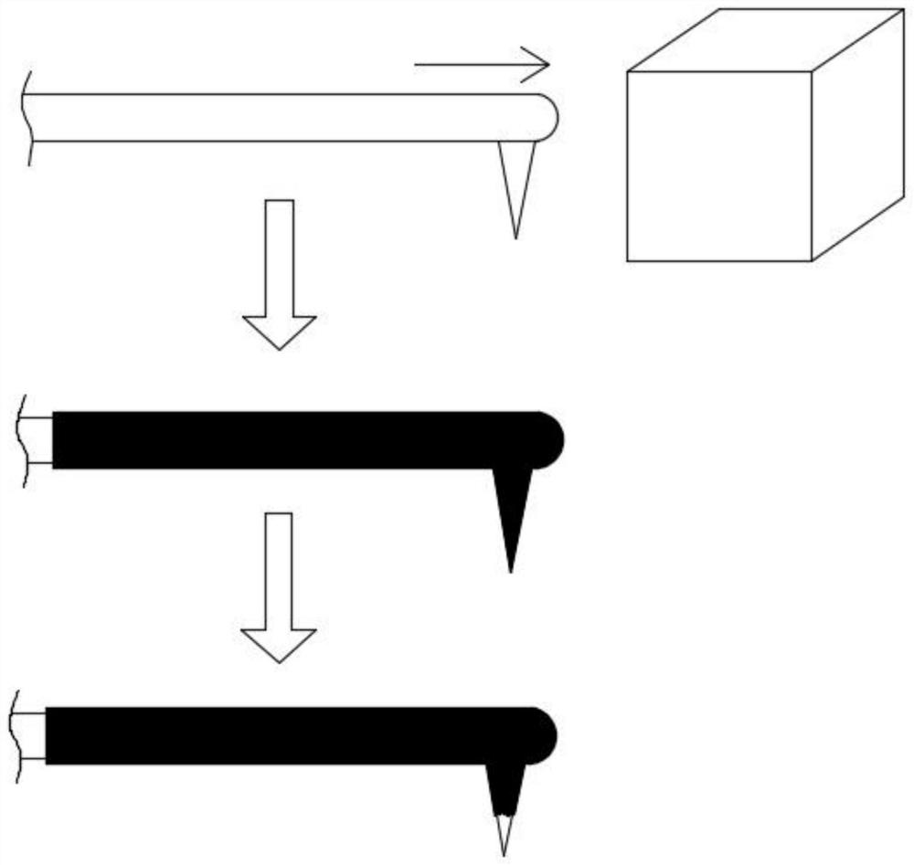
[0077] refer to figure 2 As shown, the invention discloses a real-time adjustment method for the stiffness of a probe of an atomic force microscope, comprising the following steps:

[0078] S1. The probe is heated so that the temperature of the probe is higher than the melting point of the non-conductive material. Non-conductive materials have a melting point below 100°C. The non-conductive material is resin material, polyethylene, polypropylene or rubber.

[0079] S2, immersing the heated probe in the non-conductive material and staying there;

[0080] S3. Pull out the probe from the non-conductive material. At this time, the surface of the probe is coated with a non-conductive material, stop heating the probe, and the non-conductive material solidifies and forms on the probe;

[0081] S4, scrape off the non-conductive material on the needle tip. In this embodiment, after the atomic force microscope probe "wraps" the non-conductive material, the needle tip needs to be sl...


PUM

PropertyMeasurementUnit
stiffnessaaaaaaaaaa
stiffnessaaaaaaaaaa
stiffnessaaaaaaaaaa

Abstract

The invention discloses a real-time adjustment method for the stiffness of a probe of an atomic force microscope, which comprises the following steps: coating a stiffness adjustment layer on the cantilever beam to form a cantilever-coating composite; changing the stiffness adjustment layer temperature to change the stiffness of a cantilever-coated composite. The stiffness of the probe can be adjusted in real time, without frequent replacement of the probe, reducing the loss of the probe, with a large adjustment range, a wide working range, and good stability.

Description

technical field [0001] The invention relates to the technical field of atomic force microscopes, in particular to a real-time adjustment method for the stiffness of a probe of an atomic force microscope. Background technique [0002] The atomic force microscope uses a special tiny probe to scan the surface of the sample material in the left and right and front and rear directions, and uses the scanner's ability to fine-tune in the vertical direction to keep the force between the probe and the material surface constant during the scanning process. The vertical fine-tuning distance of each point during the scanning process is recorded, and the three-dimensional topography of the material surface can be characterized. [0003] At the same time, the atomic force microscope presses the probe tip into and out of the material surface, obtains the force-displacement curve through the sensor, and calculates the curve to obtain the Young's modulus and hardness of the measured material...

Claims


Application Information

Patent Timeline
Patent Type & Authority Patents(China)
IPC IPC(8): G01Q60/38
CPCG01Q60/38
Inventor 陈科纶谷森孙钰汝长海朱军辉
Owner JIANGSU JICUI MICRO NANO AUTOMATION SYST & EQUIP TECH RES INST CO LTD
Why Eureka
Try Eureka