Foot prosthesis device with adjustable rigidity

An adjustable and rigid technology, applied in the field of medical devices, can solve the problems of increased weight of prosthetic limb structure, inability to adjust stiffness, high energy consumption, etc., to achieve the effect of ensuring compact structure, improving comfort in use, and simplifying structure

Pending Publication Date: 2020-09-22
SHANGHAI UNIV OF ENG SCI
View PDF10 Cites 1 Cited by
  • Summary
  • Abstract
  • Description
  • Claims
  • Application Information

AI Technical Summary

Problems solved by technology

[0002] At present, the foot prosthesis devices on the market are mainly divided into passive prostheses and active prostheses. Among them, passive prostheses are made of carbon fiber, and through the action of springs, the entire prosthetic structure has a certain degree of elasticity. Lightweight, but because passive prosthetics cannot match the user's movement well, it will affect the user's wearing comfort; active prosthetics are often driven by motors, specifically adding motors and control components to the prosthetic structure. Walking is natural, but due to the increase of motors and other control drive components, the weight of the prosthesis structure will increase, the structure will be complicated, and it will generate a certain amount of high energy consumption
[0003] In addition, when the user is walking or running, due to the different degree of impact between the prosthesis and the user's residual limb, it is often necessary to rely on the stiffness provided by the prosthesis to ensure the user's comfort, but whether it is a passive prosthesis that relies on springs to provide elasticity, Active prostheses still rely on motors, which cannot timely and reliably adjust the stiffness according to the user's movement conditions, and cannot guarantee the user's comfort when using the prosthesis

Method used


Image

  • Foot prosthesis device with adjustable rigidity
  • Foot prosthesis device with adjustable rigidity

Examples


Embodiment

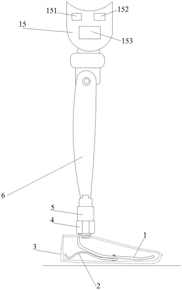
[0028] Such as figure 1 As shown, a foot prosthesis device with adjustable stiffness includes a first foot plate 1, a second foot plate 2, a foot buffer shell 3, a connector 4, a stiffness adjustment structure 5, a support rod 6 and a knee sheath 15, wherein , the first foot plate 1 and the second foot plate 2 are installed inside the foot cushioning shell 3, the first foot plate 1 is connected with one end of the second foot plate 2 through bolts to form the prosthesis body, the first foot plate 1 is connected with the connector 4 The stiffness adjustment structure 5 is connected, and the connector 4 is connected to the stiffness adjustment structure 5 by bolts. The stiffness adjustment structure 5 is installed at the position corresponding to the ankle of the prosthesis body, and the prosthesis body is connected to the knee sheath 15 through the support rod 6. An acceleration sensor 151 , a processor 152 and a controllable power supply 153 are installed, and the controllable...


PUM


Abstract

The invention relates to a foot prosthesis device with adjustable rigidity. The foot prosthesis device comprises a prosthesis body and a knee sheath which are connected through a supporting rod, wherein a rigidity adjusting structure is installed at the position, corresponding to an ankle, of the prosthesis body; the rigidity adjusting structure comprises a magnetorheological elastomer and a magnet exciting coil; an acceleration sensor, a processor and a controllable power supply which are connected in sequence are arranged in the knee sheath; the controllable power supply is connected with the magnet exciting coil; the acceleration sensor is used for collecting acceleration information of a stump of a user; the processor is used for controlling the magnitude of output current of the controllable power supply; the controllable power supply outputs current to the rigidity adjusting structure; the magnet exciting coil generates a corresponding magnetic field according to the current; andthe magnetorheological elastomer generates a rigidity change according to a magnetic field change. Compared with the prior art, the foot prosthesis device has the advantages that on the basis of an magnetorheological elastomer technology, by constructing the rigidity adjusting structure and combining the acceleration sensor, the processor and the controllable power supply, the purpose that the rigidity is automatically adjusted along with the movement condition of the user can be achieved, so that the use comfort is effectively improved.

Description

technical field [0001] The invention relates to the technical field of medical instruments, in particular to a foot prosthesis device with adjustable stiffness. Background technique [0002] At present, the foot prosthesis devices on the market are mainly divided into passive prostheses and active prostheses. Among them, passive prostheses are made of carbon fiber, and through the action of springs, the entire prosthetic structure has a certain degree of elasticity. Lightweight, but because passive prosthetics cannot match the user's movement well, it will affect the user's wearing comfort; active prosthetics are often driven by motors, specifically adding motors and control components to the prosthetic structure. Walking is natural, but due to the increase of motors and other control drive components, the weight of the prosthesis structure will increase, the structure will be complicated, and it will generate a certain amount of high energy consumption. [0003] In additio...

Claims


Application Information

Patent Timeline
Patent Type & Authority Applications(China)
IPC IPC(8): A61F2/60A61F2/64A61F2/66F16F9/53
CPCA61F2/60A61F2/64A61F2/66F16F9/535A61F2002/6614A61F2002/5004F16F2224/045
Inventor 罗一平王磊王维成熊皓
Owner SHANGHAI UNIV OF ENG SCI
Why Eureka
Try Eureka