Design method of optical pattern, an area array projection device and depth camera

A technology of optical patterns and design methods, applied in the field of optics, can solve problems such as low power consumption and small volume, and achieve the effect of strong uniformity and irrelevance

Active Publication Date: 2017-04-19
SHENZHEN ORBBEC CO LTD
View PDF5 Cites 27 Cited by
  • Summary
  • Abstract
  • Description
  • Claims
  • Application Information

AI Technical Summary

Problems solved by technology

[0003] As the application fields of depth cameras become more and more extensive, in addition to robots, drones and other equipment, depth cameras will gradually be integrated into devices such as tablets and mobile phones, which requires depth cameras to have a smaller size, more Low power consumption and stronger performance, while projection modules using a single laser light source often cannot meet this requirement

Method used


Image

  • Design method of optical pattern, an area array projection device and depth camera
  • Design method of optical pattern, an area array projection device and depth camera
  • Design method of optical pattern, an area array projection device and depth camera

Examples


no. 1 example

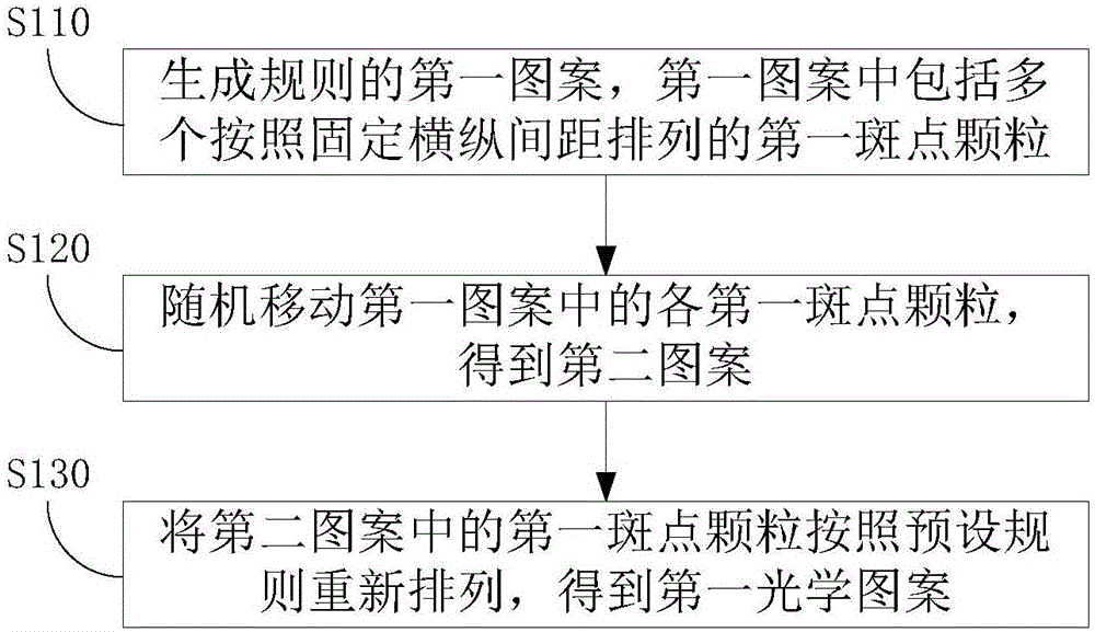
[0033] see Figure 1 to Figure 9 , the first embodiment of the design method of the optical pattern of the present invention includes:

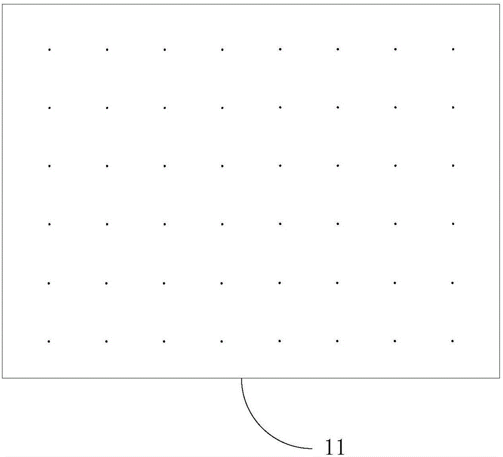
[0034] S110, generating a regular first pattern 11, where the first pattern 11 includes a plurality of first speckle particles arranged at fixed horizontal and vertical intervals;

[0035] The first pattern 11 is composed of a plurality of first speckle particles, and each first speckle particle is arranged in a uniform row and column. The pitches are also all the same as each other.

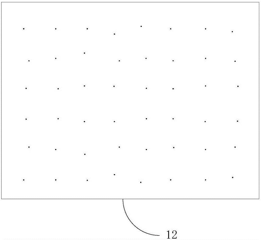
[0036] S120, randomly moving each first speckle particle in the first pattern 11 to obtain a second pattern 12;

[0037] The random movement of each first speckle particle in the first pattern 11 may be specifically moving the first speckle particle randomly within a circle whose center is the original position and whose radius is the second predetermined value. Wherein, the second predetermined value is the radius of the random movement range of the first s...


PUM


Abstract

The invention discloses a design method of an optical pattern. The method comprises the following steps of generating a first regular pattern, wherein the first pattern includes a plurality of first spot particles which are arranged according to a fixed transverse and longitudinal spacing; randomly moving each first spot particle in the first pattern and acquiring a second pattern; and rearranging the first spot particles in the second pattern according to a preset rule and acquiring a first optical pattern, wherein the first optical pattern is a light source arrangement pattern and is used for forming a composite optical pattern after the first optical pattern and a second optical pattern are combined; and the second optical pattern is the pattern formed through beam expansion of a single beam of light via a diffractive optical component. The invention also discloses an area array projection device and a depth camera. Through the above mode, the uniform composite optical pattern possessing high irrelevance can be acquired; and simultaneously the projection device made through using the design method possesses advantages of a small size, low power consumption and uniform transmission.

Description

technical field [0001] The invention relates to the field of optics, in particular to an optical pattern design method, an area array projection device and a depth camera. Background technique [0002] Depth cameras are currently widely used in somatosensory games, robotics and UAV vision systems due to their advantages such as high precision and fast acquisition speed. The depth camera includes a projection module, which generally consists of a single laser light source, a lens, and a diffractive optical element (Diffractive Optical Elements, DOE). The depth camera projects a fixed structured light speckle pattern to the target space through its projection module, and the style of the structured light speckle pattern is often determined by the DOE. [0003] As the application fields of depth cameras become more and more extensive, in addition to robots, drones and other equipment, depth cameras will gradually be integrated into devices such as tablets and mobile phones, wh...

Claims


Application Information

Patent Timeline
Patent Type & Authority Applications(China)
IPC IPC(8): G02B27/00G02B27/42G03B21/20G01B11/25
CPCG01B11/254G02B27/0012G02B27/425G03B21/2033
Inventor 黄源浩刘龙肖振中许星
Owner SHENZHEN ORBBEC CO LTD
Why Eureka
Try Eureka