
Multi-freedom-degree spectral filter capable of compensating chromatic dispersion of polarization mode

A polarization mode dispersion, spectral filter technology, applied in instruments, optics, static indicators, etc., can solve the problems of difficult adjustment of the free spectral region, complex adaptive control system, etc., to achieve the effect of suppressing the effect of amplitude-frequency modulation

Active Publication Date: 2017-04-19
SHANGHAI INST OF OPTICS & FINE MECHANICS CHINESE ACAD OF SCI
View PDF5 Cites 2 Cited by
  • Summary
  • Abstract
  • Description
  • Claims
  • Application Information

AI Technical Summary

Problems solved by technology

[0004] The purpose of the present invention is to overcome the deficiencies of the above-mentioned prior art, and provide a multi-degree-of-freedom spectral filter capable of compensating polarization mode dispersion, which is used to solve the problems of difficult adjustment of the free spectral region and complex adaptive control system of the existing polarization mode dispersion compensation device. question

Method used


Image

  • Multi-freedom-degree spectral filter capable of compensating chromatic dispersion of polarization mode
  • Multi-freedom-degree spectral filter capable of compensating chromatic dispersion of polarization mode
  • Multi-freedom-degree spectral filter capable of compensating chromatic dispersion of polarization mode

Examples


Embodiment 1

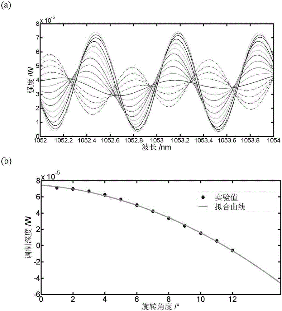
[0023] Embodiment 1: as attached figure 1 As shown, a multi-degree-of-freedom spectral filter that can compensate polarization mode dispersion includes a fiber collimator 1 with a central wavelength of 1053nm, a film polarizer 2 with a transmission wavelength of 550-1500nm, and a clear aperture Half-wave phase liquid crystal with a transmission wavelength of 1050-1700nm 3, a second optical fiber collimator whose pigtail is a 1053nm polarization-maintaining fiber 4, an additional polarization-maintaining fiber with a transmission wavelength of 1053nm 5, a polarization-maintaining fiber spliced ​​after the optical axis is rotated by 45° Polarized optical fiber 6 and optical fiber analyzer 7 whose pigtail is 1053nm polarization-maintaining optical fiber.

[0024] When the group velocity dispersion and loss introduced by the optical fiber are not considered, the system filter function of the filter can be expressed as

[0025] h out (f)=M ILP M CON M PM-R-PM M CON M PM M ...

Embodiment 2

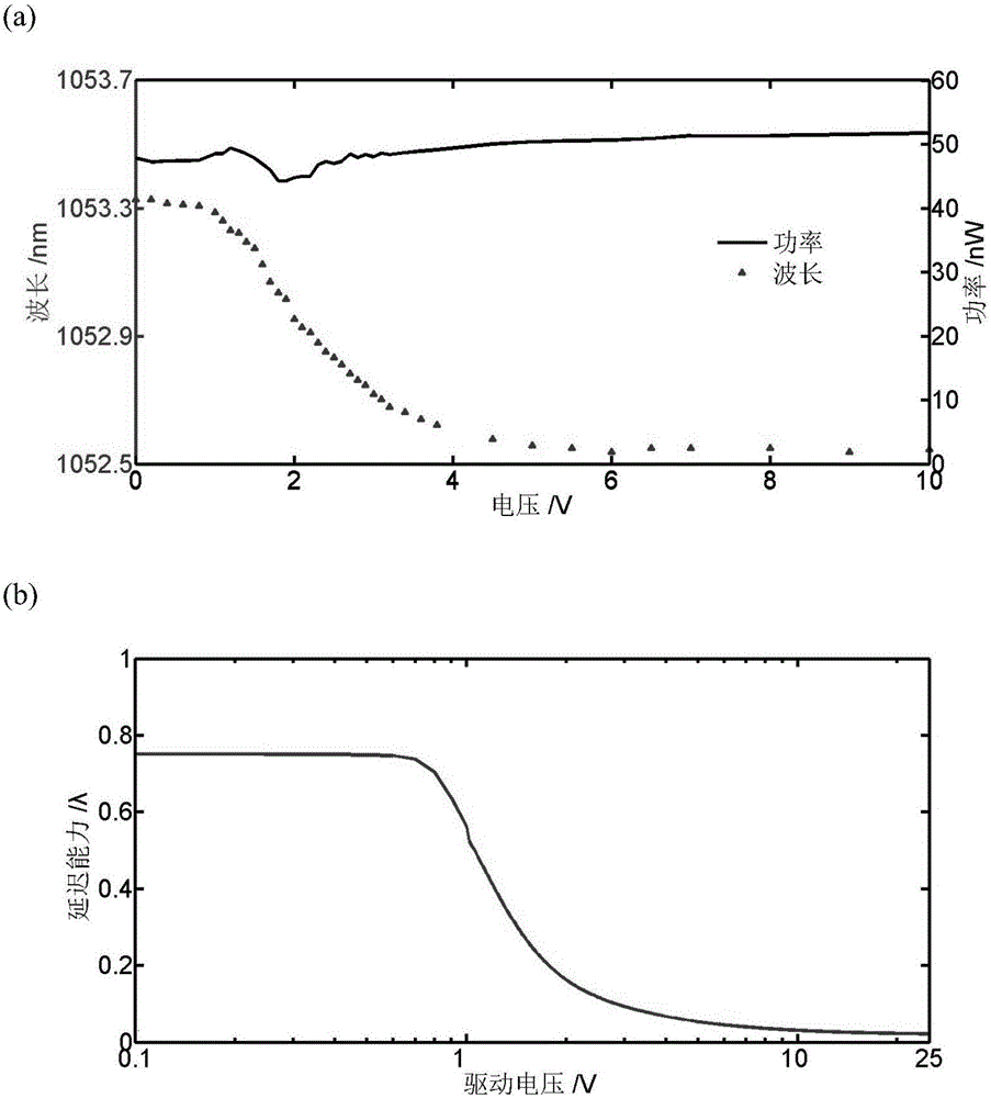
[0034] Embodiment 2: Investigate the peak wavelength decoupling tuning capability of the filter. The implementation conditions are the same as in Example 1, but the angle of the film polarizer is kept constant, and the length of the additional polarization-maintaining fiber is 3 m. Gradually increase the voltage value applied to the liquid crystal, and obtain the schematic diagram of the change of the peak wavelength and peak power of the filter with the liquid crystal voltage as attached image 3 shown. It can be seen from the figure that during the adjustment, the peak power of the filter hardly changes, indicating that the modulation depth does not change with the liquid crystal voltage, that is, the decoupling tuning of the peak wavelength is realized. image 3 (a) is the change curve of peak wavelength and peak power with liquid crystal pressure; image 3 (b) is the variation curve of liquid crystal retardation performance with applied voltage. Comparing the two curves...

Embodiment 3

[0035] Embodiment 3: Investigate the change of the free spectral range of the filter with the change of the length of the additional polarization-maintaining fiber. The implementation conditions are the same as in Example 1, but the angle of the film polarizer and the voltage value applied by the liquid crystal are kept constant, and different additional polarization-maintaining fiber lengths are replaced to obtain a schematic diagram of the change of the peak wavelength and peak power of the filter with the voltage of the liquid crystal as attached Figure 4 shown. The required additional polarization-maintaining fiber length can be calculated according to the formula: Δν=1 / εl according to the required free spectral range, and the conversion relationship when the free spectral range is expressed by frequency and wavelength satisfies: In use, it should be noted that l in the formula is the sum of the total lengths of the second collimator pigtail, the additional polarization-...


PUM


Abstract

The invention provides a multi-freedom-degree spectral filter capable of compensating chromatic dispersion of a polarization mode. The filter comprises a first optical fiber collimator, a thin-film polarizer, a phase type liquid crystal, a second optical fiber collimator, an additional polarization maintaining fiber, a polarization maintaining optical fiber with an optical axis rotating and an optical fiber analyzer. The thin-film polarizer is rotated and the voltage of the phase type liquid crystal and the length of the additional polarization maintaining fiber are adjusted, thereby realizing decoupling adjustment on the modulation depth, the peak wavelength and the free spectral range of the filter. The multi-freedom-degree spectral filter has height controllability. The multi-freedom-degree spectral filter can be used for compensating an amplitude and frequency modulation effect caused by chromatic dispersion of a fiber polarization mode when wide-spectrum light in a high-power laser system is transmitted in a polarization-maintaining device and a polarization-maintaining fiber. When the multi-freedom-degree spectral filter is in use, according to a time-domain waveform monitored by an oscilloscope, a controller is controlled based on a computer feedback to adjust a parameter of a compensation unit, thereby realizing automatic real-time compensation of chromatic dispersion of a polarization mode.

Description

technical field [0001] The invention relates to the field of spectral filter devices, in particular to a multi-degree-of-freedom spectral filter capable of compensating polarization mode dispersion. Background technique [0002] In the field of lasers, especially in the field of high-power lasers, in order to control the generation of nonlinear effects and achieve smoothing of the focal spot, it is necessary to use a phase modulator to broaden the spectrum of the single-frequency laser. However, the polarization-maintaining device in the laser system and the polarization-mode dispersion (including differential group delay and low polarization extinction ratio) in the polarization-maintaining fiber will produce a polarization filtering effect, so that different spectral components in the broadened spectrum The non-uniform transmission, when reaching the output, causes the frequency-modulated part of the laser to convert to amplitude modulation, a phenomenon known as the ampli...

Claims


Application Information

Patent Timeline
Patent Type & Authority Applications(China)
IPC IPC(8): G02F1/133G02F1/1335G02F1/13363
CPCG02F1/13306G02F1/133528G02F1/13363G02F1/133531
Inventor 李娆范薇乔治黄灿鸿
Owner SHANGHAI INST OF OPTICS & FINE MECHANICS CHINESE ACAD OF SCI
Learn More