Wireless access system

A wireless access system and remote wireless head-end technology, applied in radio transmission systems, diversity/multi-antenna systems, transmission systems, etc., can solve problems such as non-existent solutions, achieve improved capacity performance, cost economy, and reduce installation difficulties Effect

Active Publication Date: 2017-04-19
ALCATEL LUCENT SHANGHAI BELL CO LTD
View PDF6 Cites 7 Cited by
  • Summary
  • Abstract
  • Description
  • Claims
  • Application Information

AI Technical Summary

Problems solved by technology

[0006] To date, no good solution exists for BBU centralized indoor wireless access de...

Method used


Image

  • Wireless access system
  • Wireless access system
  • Wireless access system

Examples


Embodiment Construction

[0040] The principle and spirit of the present disclosure will be described below with reference to several exemplary embodiments shown in the accompanying drawings. It should be understood that these specific embodiments are described only to enable those skilled in the art to better understand and realize the present disclosure, rather than to limit the scope of the present disclosure in any way.

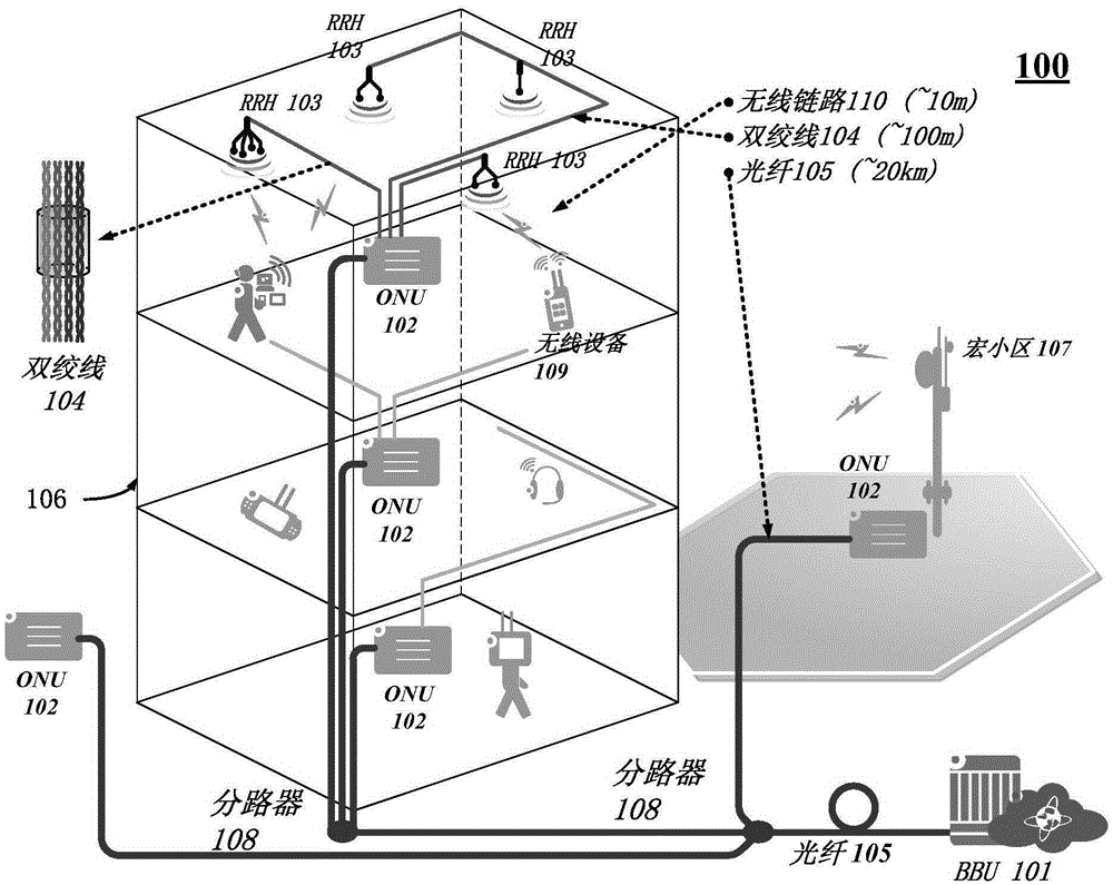
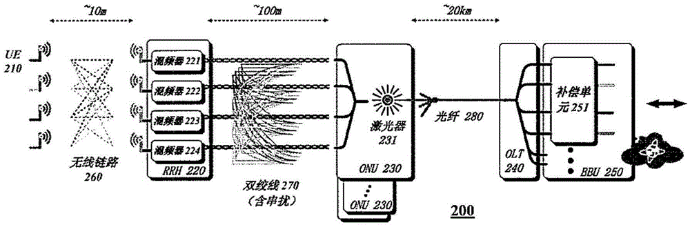
[0041] As described above, for the current indoor distributed antenna system DAS, coaxial cables are widely used as the last 100 meters of fixed channels connecting many antenna units to a common baseband processing unit pool BBU. It has been noticed that the following two disadvantages limit the deployment of indoor DAS.

[0042] First, the use of coaxial cables is considered to be cost inefficient because of the high price of coaxial cables and the number required in future indoor wireless deployment scenarios will be very large. Second, the data streams fed to and from all ant...


PUM


Abstract

The embodiment of the disclosure provides a wireless access system that may include a baseband unit (BBU), an optical network unit (ONU), and a remote radio head (RRH), wherein the BBU may be connected to one or more ONUs, each ONU may be connected to one or more RRHs, and the connection between each ONU and the one or more RRHs can achieved by twisted pairs. The wireless access system is capable of providing large-capacity access, convergence and transmission from an indoor antenna unit to the centralized BBUs, and is easy to install so that large-scale deployment of indoor wireless access is economical. In addition, the wireless access system can support advanced wireless technologies, such as large-scale MIMO, CoMP and the like. The embodiments of the present disclosure also provide a RRH, an ONU, an optical line terminal (OLT), and a BBU.

Description

technical field [0001] Embodiments of the present disclosure relate generally to wireless communications, and more particularly to a wireless access system, a remote wireless head-end, an optical network unit, an optical line terminal, and a pool of baseband processing units. Background technique [0002] With technological and commercial advances in mobile data services, it has been noted that more than 70% of wireless services are consumed indoors. The currently dominant indoor wireless access solution is a Distributed Antenna System (DAS) or a small cell system. However, both methods have disadvantages. For DAS, the data streams fed to and from different antennas are the same, making this scheme good in coverage and cheap in deployment, but limited in capacity. For the indoor small cell system, because the BBU is distributed and co-located with the wireless head-end, on the one hand, the wireless head-end is very complicated and expensive, and on the other hand, it is n...

Claims


Application Information

Patent Timeline
IPC IPC(8): H04B7/26H04B7/0413
CPCH04B7/024H04B7/0413H04B7/2609H04W88/085H04B10/25754H04B3/32H04B10/25753H04B10/2589H04L12/2885
Inventor 叶晨晖胡小锋张凯宾
Owner ALCATEL LUCENT SHANGHAI BELL CO LTD
Why Eureka
Try Eureka