An automatic detection device for the glue head of a frame gluing machine

A technology of automatic detection device and gluing machine, which is applied to the device and coating of the surface coating liquid, can solve the problem of automatic equipment that has not yet appeared to detect the glue head of the frame gluing machine, increase the labor intensity of the staff, and increase the batch size. Problems such as poor quality of components can eliminate hidden troubles, reduce labor intensity and have a simple structure.

Active Publication Date: 2019-05-10
JA XINGTAI SOLAR CO LTD
View PDF6 Cites 0 Cited by
  • Summary
  • Abstract
  • Description
  • Claims
  • Application Information

AI Technical Summary

Problems solved by technology

[0005] ⑴ Special personnel are required to monitor the post, which increases the labor intensity of the staff
[0006] ⑵When the staff monitoring is not in place, it is easy to cause poor quality of batch components or even scrap components
[0007] At present, there is no automatic equipment specially used to detect the glue head of the frame glue machine in this industry.

Method used


Image

  • An automatic detection device for the glue head of a frame gluing machine
  • An automatic detection device for the glue head of a frame gluing machine
  • An automatic detection device for the glue head of a frame gluing machine

Examples


Embodiment 1

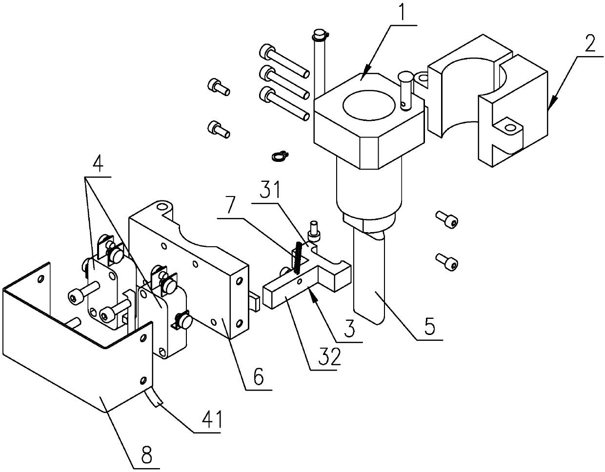
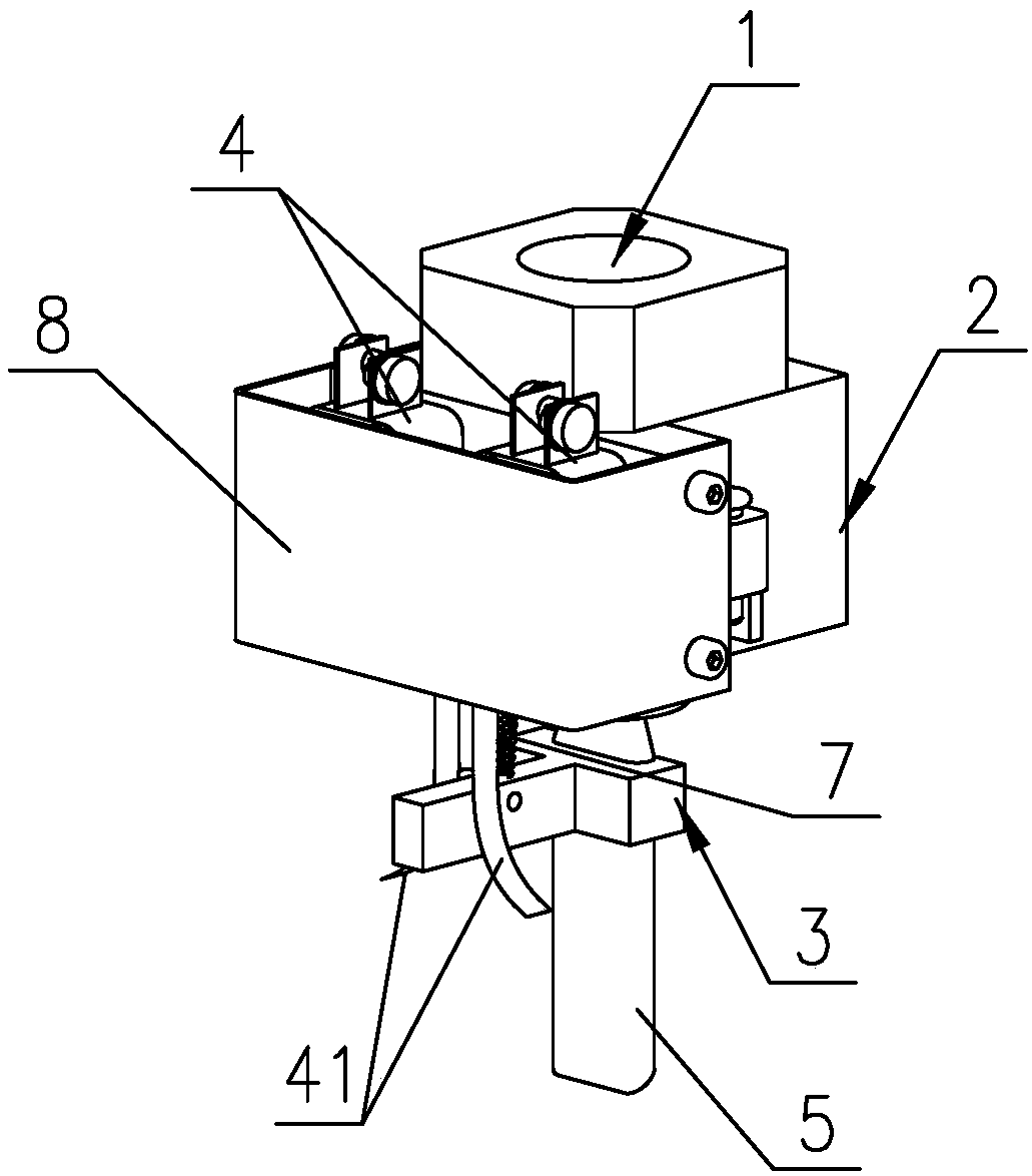
[0026] Such as figure 1 and 2 As shown, it is an automatic detection device for the glue head of the frame glue machine of the present invention, which includes a ferrule 2 for being installed on the glue valve 1 of the frame glue machine, a linkage rod 3 and a pair of parallel microswitches 4 , the pair of microswitches 4 are installed on the outer wall of the ferrule 2, each microswitch 4 has a driving rod 41 protruding downward, and the two driving rods 41 are symmetrically arranged side by side with a gap between them, the microswitch 4. Connect with the controller of the frame glue machine. The linkage rod 3 is arranged horizontally and under the ferrule 2. The linkage rod 3 is composed of a chuck 31 with a slot and a rod 32 connected to the chuck 31 at one end. , the card slot of the chuck 31 is engaged on the rubber head 5 of the frame gluer, and the other end of the rod 32 extends into the gap between the driving rods 41 of the pair of micro switches 4 and sticks clos...

Embodiment 2

[0039] The difference between this embodiment and Embodiment 1 is that the specific structure of the micro switch installed on the outer wall of the main body is different, that is, a pair of positioning rods are arranged side by side on the upper part of the outer wall of the main body, and the pair of micro switches have a positioning rod respectively. hole, the positioning rod correspondingly penetrates into the positioning hole, a block is provided on the lower part of the outer wall of the main body, a groove is provided between the pair of micro switches, the block is engaged in the groove, and the distance between the main body and the pair of micro switches One end of the limit spring is fixed on the outer wall of the main body, the other end is fixed on the micro switch, and the limit spring is vertically arranged. It is mainly composed of the first section, the horizontal section, the oblique section connected in sequence The first section is perpendicular to the main...


PUM


Abstract

The invention discloses an automatic detecting device for an adhesive applying head of a frame adhesive applying machine. The automatic detecting device comprises a ferrule, a linkage rod and micro-switches, wherein the pair of micro-switches are mounted on the outer wall of the ferrule, each micro-switch is provided with a driving rod extending downwards, the two driving rods are symmetrically arranged, a clearance is arranged between the driving rods, and the micro-switches are connected with a controller; the linkage rod is transversely arranged and located below the ferrule, and the linkage rod consists of a chuck provided with a clamping groove and a rod part of which one end is connected with the chuck; and the chuck is used for being buckled on the adhesive applying head of the frame adhesive applying machine, and the other end of the rod part extends into the clearance between the driving rods of the micro-switches. The adhesive applying head of the frame adhesive applying machine is bent under the action of external force in the movement direction and drives the linkage rod to correspondingly move. After the driving rods are shifted, the micro-switches are triggered, the micro-switches send trigger signals to the controller, and the controller controls the frame adhesive applying machine to stop acting. The automatic detecting device is accurate in detection, ensures product quality, reduces labor intensity, improves equipment automation degree and is suitable for being widely popularized and used in the industry.

Description

technical field [0001] The invention relates to an automatic detection device for the rubber head of a frame gluer. Background technique [0002] The solar photovoltaic industry uses the aluminum frame as the frame support of the solar cell module to protect the module. In the framing process of crystalline silicon solar cell modules, in order to ensure the sealing performance of crystalline silicon solar cell modules, it is necessary to inject sealant into the installation groove of the aluminum frame, and then set the installation groove of the aluminum frame on the edge of the laminate, so that the The aluminum frame and components are bonded and sealed. [0003] At present, frame gluing machines are widely used to bond and seal the aluminum frame and components. The existing frame gluing machines generally include a frame, a rubber cartridge, a motor, a transmission mechanism, a rubber valve for controlling the amount of glue output, and a rubber valve for the output. ...

Claims


Application Information

Patent Timeline
Patent Type & Authority Patents(China)
IPC IPC(8): B05C5/02
CPCB05C5/02
Inventor 晋世森董国斌胡静亮尹建仓李松
Owner JA XINGTAI SOLAR CO LTD
Why Eureka
Try Eureka