Eureka AIR delivers breakthrough ideas for toughest innovation challenges, trusted by R&D personnel around the world.

Automatic cord clamping device for steel cord wrapping machine

A technology of outer winding machine and steel cord, applied in the field of steel cord production, can solve the problems of increasing the amount of semi-finished products, the strong magnetic adsorption device cannot fix the cord, and the hidden danger of product quality, so as to ensure normal operation and prevent return. The effect of shrinking phenomenon and eliminating accumulation

Inactive Publication Date: 2017-04-26
JIANGSU XINGDA STEEL TYPE CORD
View PDF6 Cites 2 Cited by
  • Summary
  • Abstract
  • Description
  • Claims
  • Application Information

AI Technical Summary

Problems solved by technology

[0002] In the current steel cord outer winding process, the I-shaped wheel is used to pay off the wire and the FP lubricant is used for the outer winding. After the machine tool is stopped, the cord cutting needs to be inspected. The arm rebounds due to the tension, so that the cord wound on the machine tool will retract about 5mm as a whole. When driving again, the outer winding wire at the outer winding head of the outer winding spindle will continue to rotate and accumulate at the same point of the cord, which will cause damage to the product. Serious hidden dangers in quality; if VSV or ADMU lubricant is used for the outer winding wire, the cord retraction phenomenon is not obvious, and the accumulation of the outer winding wire will not be formed, but the length of the broken wire after twisting the cord will be significantly reduced and the semi-finished product will be increased. quantity
At present, the φ25*5 strong magnetic adsorption device used at the take-up place of the outer winding machine cannot play the role of fixing the cord, and the retraction of the cord cannot be avoided; affect product quality

Method used


Image

  • Automatic cord clamping device for steel cord wrapping machine

Examples


Embodiment Construction

[0008] The specific structure and characteristics of the automatic wire clamping device of the steel cord outer winding machine of the present invention will be further described below with reference to the accompanying drawings.

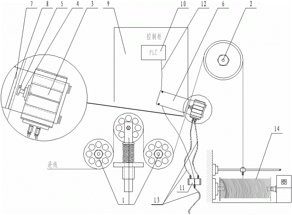
[0009] see figure 1 A schematic diagram of the composition of an automatic wire clamping device for a steel cord outer winding machine according to an embodiment of the present invention is shown. The pneumatic wire clamping device between the force arm guide wheels 2, the pneumatic wire clamping device includes a cylinder 3, a cylinder shaft 4, a first polyurethane gasket 5, a fixing bracket 6, a baffle 7 and a second polyurethane gasket 8, so The first polyurethane gasket 5 is arranged on the cylinder shaft 4, and the second polyurethane gasket 8 is arranged on the baffle plate 7; the pneumatic thread clamping device is fixed with the outer winding machine through the fixing bracket 6; the pneumatic thread clamping device is The solenoid valve 11...


PUM


Abstract

The invention provides an automatic cord clamping device for a steel cord wrapping machine. The automatic cord clamping device for the steel cord wrapping machine comprises a pneumatic cord clamping device arranged between tension guide wheels and a moment arm guide wheel of the wrapping machine, wherein the pneumatic cord clamping device comprises a cylinder, a cylinder shaft, a first polyurethane gasket, a fixing support, a baffle and a second polyurethane gasket; the first polyurethane gasket is arranged on the cylinder shaft; the second polyurethane gasket is arranged on the baffle; the pneumatic cord clamping device and the wrapping machine are fixed through the fixing support; the pneumatic cord clamping device is connected with a solenoid valve through a vent pipe; and the solenoid valve is connected with a PLC module in a machine tool control cabinet of the wrapping machine through a control wire. By the automatic cord clamping device, a cord can be automatically clamped in time when equipment stops, and retraction of the cord is completely eradicated effectively; when running of the equipment recovers, the cord can be released automatically, and normal running of the wrapping machine is guaranteed; and accumulation of external wrapping wires of cords is completely eradicated, negative hidden dangers are avoided, and the quality of products is stabilized.

Description

technical field [0001] The invention relates to the technical field of steel cord production, in particular to an automatic wire clamping device for a steel cord outer winding machine. Background technique [0002] In the current steel cord outer winding process, the I-shaped wheel is used to pay off the wire and the FP lubricant is used for the outer winding. After the machine tool is stopped, the cord cutting needs to be checked. The arm springs back due to the tension, so that the cord wound on the machine tool is retracted by about 5MM as a whole. When driving again, the outer winding wire at the outer winding head of the outer winding spindle will continuously rotate and accumulate at the same point of the cord, giving the product to the product. It will bring serious quality risks; if the outer winding of VSV or ADMU lubricant is used, the retraction of the cord will not be obvious, and the accumulation of the outer winding will not be formed, but the length of the twi...

Claims


Application Information

Patent Timeline
IPC IPC(8): B21F3/04
CPCB21F3/04
Inventor 马爱国刘国平翁绍宏汤恒威
Owner JIANGSU XINGDA STEEL TYPE CORD
Why Eureka
Eureka Blog
Learn More