A cooling structure for a busbar mold

A technology of cooling structure and bus bar, which is applied in the field of cooling structure, can solve the problems of different cooling effects, large cooling effect, large temperature difference fluctuation, etc., and achieve the effect of high cooling efficiency, elimination of influence, and reduction of contact

Active Publication Date: 2018-11-23
ZHEJIANG HAIYUE AUTOMATIC MACHINERY
View PDF9 Cites 2 Cited by
  • Summary
  • Abstract
  • Description
  • Claims
  • Application Information

AI Technical Summary

Problems solved by technology

[0002] In the battery industry, especially the lead-acid battery industry, commonly used parts include tabs and matching busbars. In the traditional manufacturing process of busbars, it is necessary to prepare busbar molds and lead pots. The busbars of this process The manufacturing efficiency of the row is very low, and the actual casting and welding effect is very poor. At the same time, because the mold is immersed in the lead pot, it needs to be cooled after the casting and welding is completed. The traditional cooling uses air cooling, which is very unsatisfactory and inefficient.
[0003] In the prior art, the circulation pipe is used for cooling. The liquid inlet pipe is connected to the liquid inlet pipe from one side of the mold. The pipeline cools the forming grooves of two different casting and welding parts separately. Since the temperature of the inlet and outlet pipelines is different, the cooling effect is also different, which has a great impact on casting and welding.
[0004] For example, the Chinese patent document with the authorized announcement number CN 202210457 U discloses a water cooling device for busbars, which uses water inlet pipes and outlet pipes to cool down busbars. However, such a water cooling device has the following disadvantages: First, it consumes a lot of resources , Cooling water consumes several tons a day. Secondly, water cooling is carried out in the state of high temperature of the mold. The temperature difference fluctuates greatly, and the mold is prone to cracks. Thirdly, in the process of busbar production, the temperature control is more strict and personalized. , there are some cooling links to cool down the equipment, but the temperature should not be too low, and the cooling effect of water cooling is large and rapid, and it is easy to cool down transitionally, which will affect the heating up of the equipment again

Method used


Image

  • A cooling structure for a busbar mold
  • A cooling structure for a busbar mold
  • A cooling structure for a busbar mold

Examples


Embodiment 1

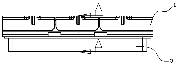
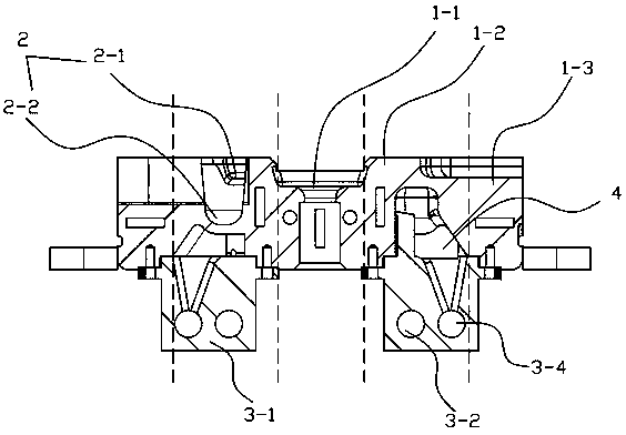
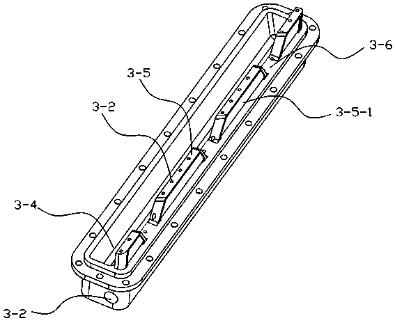
[0025] Embodiment one, such as Figure 1 to Figure 3 As shown, the embodiment of the present invention includes a mold body 1, a plurality of linearly arranged molding grooves 2 are arranged on the mold body 1, and a cooling device 3 is arranged below the molding groove 2, and it is characterized in that: the mold body 1 includes a Groove 2 is a constant temperature area 1-1 for lead supply, a casting welding area 1-2 for casting welding, and a heat preservation area for insulating the casting welding area 1-2. The forming tank 2 is arranged in the casting welding area 1-2, The constant temperature zone 1-1, the casting and welding zone 1-2 and the heat preservation zone are independently equipped with heaters, and the heater mainly adopts a ceramic heating body. Each casting and welding zone 1-2 is correspondingly equipped with an independent cooling device 3, and the cooling device 3 includes the cooling body 3-1 arranged under the casting and welding zone 1-2 and / or the hea...


PUM


Abstract

The invention provides a cooling structure of a busbar mold. The cooling structure of the busbar mold comprises a mold body. A plurality of forming grooves are linearly formed in the mold body. Cooling devices are arranged below the forming grooves. The cooling structure of the busbar mold is characterized in that the mold body comprises a constant-temperature area, cast welding areas and heat preservation areas. The forming grooves are formed in the cast welding areas. One independent cooling device is correspondingly arranged in each cast welding area. Each cooling device comprises a cooling body which is arranged below the corresponding cast welding area and / or the corresponding heat preservation area, wherein a liquid inlet pipe is arranged on the cooling body in the arrangement direction of the corresponding forming groove, and a water injection nozzle is arranged on the liquid inlet pipe and faces the bottom of the corresponding forming groove; and a backflow groove is further formed in the cooling body, and the backflow groove is lower than the water injection nozzle. According to the cooling structure of the busbar mold, cooling systems independently correspond to the cast welding areas are arranged, so that cooling consistency of the different cast welding areas is ensured while the cooling efficiency is improved, constant-temperature control of the mold is facilitated, and thus the cast welding effect is improved.

Description

technical field [0001] The invention relates to the field of polar plate casting and welding equipment, in particular to a cooling structure for a busbar mould. Background technique [0002] In the battery industry, especially the lead-acid battery industry, commonly used parts include tabs and matching busbars. In the traditional manufacturing process of busbars, it is necessary to prepare busbar molds and lead pots. The busbars of this process The manufacturing efficiency of the row is very low, and the actual casting and welding effect is very poor. At the same time, because the mold is immersed in the lead pot, it needs to be cooled after the casting and welding is completed. The traditional cooling uses air cooling, which is very unsatisfactory and inefficient. [0003] In the prior art, the circulation pipe is used for cooling. The liquid inlet pipe is connected to the liquid inlet pipe from one side of the mold. The pipeline cools the forming grooves of two different...

Claims


Application Information

Patent Timeline
Patent Type & Authority Patents(China)
IPC IPC(8): B22D27/04B22D19/04
CPCB22D19/04B22D27/04
Inventor 李雪锋林雁斌周国华甘小虎陈丁鹏张承建陆建兵范富强李跃波肖志新阮先金季成
Owner ZHEJIANG HAIYUE AUTOMATIC MACHINERY
Why Eureka
Try Eureka