
Machining method of rolling wheel type mechanical plate shearing machine supporting mechanism

A technology of mechanical shearing machine and support mechanism, which is applied in the field of shearing machine processing, can solve the problems of lack of fixed support points and insufficient strength of wallboards on both sides, and achieve the effects of easy promotion and use, guaranteed strength, and reduced thermal deformation

Active Publication Date: 2017-04-26
安徽金大进重工机床有限公司
View PDF9 Cites 0 Cited by
  • Summary
  • Abstract
  • Description
  • Claims
  • Application Information

AI Technical Summary

Problems solved by technology

However, for mechanical shearing machines, the pressing mechanism is fixed with the tool holder, and the pressing mechanism is driven by the knife holder to move. It is difficult to directly install a horizontal pressing plate on the outside of the main connecting plate, and there is a lack of fixed support points; on the other hand , the strength of the wall panels on both sides is insufficient, and it is difficult to use the three-point support structure of the roller type on the mechanical shearing machine

Method used


Image

  • Machining method of rolling wheel type mechanical plate shearing machine supporting mechanism
  • Machining method of rolling wheel type mechanical plate shearing machine supporting mechanism
  • Machining method of rolling wheel type mechanical plate shearing machine supporting mechanism

Examples


Embodiment 1

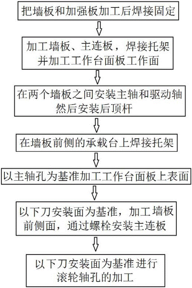
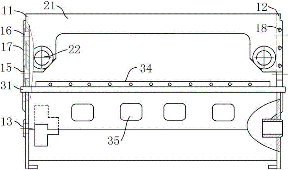
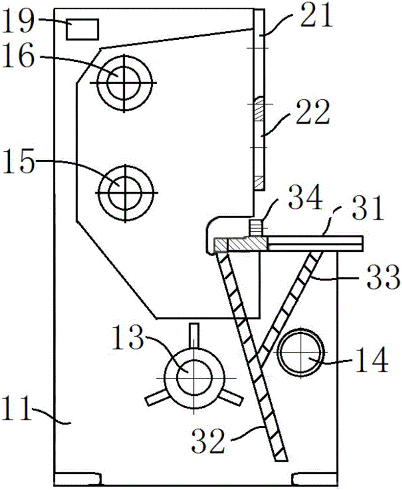
[0041] combine figure 2 with image 3 , the supporting mechanism of the roller-type mechanical shearing machine to be processed in this embodiment includes two wall panels arranged in parallel, and also includes a main connecting plate 21 and a bracket. The bracket is welded and connected to the bearing platform on the front side of the wall panel. The plate 21 is bolted to the upper section of the front side of the wallboard, that is, the upper section facing the side of the workbench panel. The main shaft hole 13 and the power shaft hole 14 are arranged on the wall board. The two shaft holes are used for installing the main shaft and connecting the drive of the motor. axis. The wallboard is also provided with a lower roller shaft hole 15 and an upper roller shaft hole 16, and the lower roller shaft hole 15 and the upper roller shaft hole 16 are located on the same vertical line for installing rollers; the two ends of the main connecting plate 21 are provided with The prot...

Embodiment 2

[0068] The processing method of a support mechanism of a roller type mechanical shearing machine in this embodiment is basically the same as that of Embodiment 1, the difference is that when welding the knife seat adjustment seat 34 on the workbench panel 31, first use The intermittent welding method is used for welding, and then the overall welding is carried out.

[0069] Such as Figure 4 As shown, that is, welding is performed in multiple welding sections, rather than welding the entire weld seam at one time. Specifically, the length of the welding section during intermittent welding is 150-220 mm, and the interval is 280-400 mm. Depending on the length of the shearing machine, it can be selected according to the actual situation. In this embodiment, the length of the welding section is 200 mm, and the interval is 320 mm.

[0070] Intermittent welding will cause some local deformation, but due to the short welding time, the accumulated heat is less and will not affect the...


PUM

PropertyMeasurementUnit
lengthaaaaaaaaaa

Abstract

The invention discloses a machining method of a rolling wheel type mechanical plate shearing machine supporting mechanism and belongs to the field of plate shearing machine machining. A reinforcing plate is connected to each wall plate of the plate shearing machine supporting mechanism, and the reinforcing plates can be used for mounting transverse rolling wheels thereon. The main machining method of the supporting mechanism comprises the steps of firstly, machining the wall plates and the reinforcing plates, and completing welding; then, machining rolling wheel shaft holes in the wall plates and a main connection plate; then, mounting a main shaft and a driving shaft; then, welding and mounting a supporting bracket; conducting datum plane machining on a mounted rack; and after the main connection plate is mounted, conducting integral machining, wherein dimensional precision of the rolling wheel shaft holes is guaranteed. According to the method, the rack structure and the machining process are improved, so that the fixation requirement of the rolling wheels is met, and sufficient structural strength is provided; in addition, machining precision is high; and it is helpful to improve machining quality of products obtained through a plate shearing machine and prolong the service life of the plate shearing machine.

Description

technical field [0001] The invention relates to the technical field of shearing machine processing, and more specifically, relates to a processing method for a support mechanism of a roller-type mechanical shearing machine. Background technique [0002] According to the power type, the shearing machine is divided into hydraulic shearing machine and mechanical shearing machine. The hydraulic shearing machine mainly relies on two hydraulic cylinders to drive the movement of the upper tool holder, so as to realize the shearing of the plate. It has stable performance, but the processing efficiency Low; the mechanical shearing machine is driven by a motor, and the knife holder moves up and down along the slide rail. The mechanical shearing machine has sufficient power and high efficiency, but the knife holder wears a lot and the noise is loud. In order to optimize the performance of the mechanical shearing machine, a three-point support can be used instead of the slide rail to me...

Claims


Application Information

Patent Timeline
Patent Type & Authority Applications(China)
IPC IPC(8): B23P15/00
CPCB23P15/00
Inventor 王大进严长贵
Owner 安徽金大进重工机床有限公司
Learn More