Supercharge Your Innovation With Domain-Expert AI Agents!

Vehicle speed limiting system and method

A vehicle speed limit and vehicle body stabilization system technology, applied in the field of vehicle speed limit systems, can solve the problems of poor applicability, driving safety, and low utilization rate of the speed limit function, so as to reduce the driving burden, ensure reliability and accuracy, and ensure driving. safety effect

Inactive Publication Date: 2017-04-26
ZHEJIANG GEELY HLDG GRP CO LTD +1
View PDF5 Cites 6 Cited by
  • Summary
  • Abstract
  • Description
  • Claims
  • Application Information

AI Technical Summary

Problems solved by technology

[0002] Drivers are prone to mental fatigue during long-time driving, and mental distraction and driving fatigue often cause drivers to step on the accelerator too deeply without knowing it, resulting in overspeeding. For drivers, overspeeding not only brings The trouble of speeding tickets, but also the hidden dangers of driving safety
[0003] However, the existing vehicle speed limit method is mainly a mechanical way by limiting the opening of the accelerator pedal. Therefore, the driver will have a sense of mechanical hindrance when stepping on the accelerator pedal, and the mechanical hindrance will easily lead the driver to understand mechanical failure. As a result, the utilization rate of the speed limit function is low, the applicability is poor, and the safety problem of driving cannot be really solved.

Method used


Image

  • Vehicle speed limiting system and method
  • Vehicle speed limiting system and method

Examples


Embodiment Construction

[0036] In order to further illustrate the technical means and effects adopted by the present invention to achieve the predetermined purpose of the invention, the specific embodiments, structures, features and effects of the present invention are described in detail below with reference to the accompanying drawings and preferred embodiments.

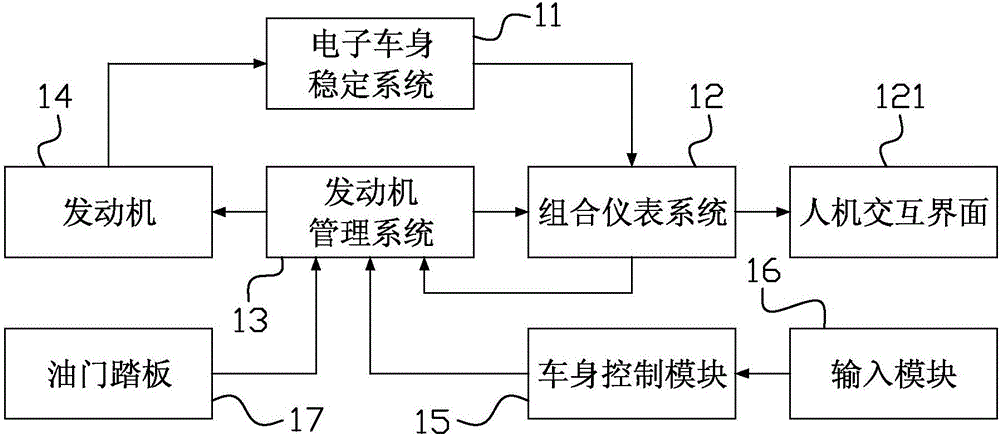
[0037] figure 1 It is a schematic diagram of the structure of the vehicle speed limit system provided by the embodiment of the present invention. like figure 1 As shown, the vehicle speed limiting system of the present invention includes an electronic body stability system (Electronic Stability Program, ESP) 11, a combination instrument system 12, an engine management system (Engine Management System, EMS) 13, an engine 14, a vehicle body control module (Body Control Module , BCM) 15, input module 16, accelerator pedal 17 and wheel speed sensor (not shown). Among them, the combined instrument system 12 includes a human machine interface...


PUM


Abstract

The invention provides a vehicle speed limiting system and method. The vehicle speed limiting system can comprise an electronic body stabilizing system, a combined instrument system, an engine management system and an engine, which are connected with each other in sequence in a closed loop. After receiving a vehicle speed setting signal, the combined instrument system sets and displays a target limited vehicle speed on a human-computer interface and transmits the target limited vehicle speed to the engine management system; after an instrument indicated vehicle speed is calculated according to an actual vehicle speed transmitted by the electronic body stabilizing system during the running of a vehicle, the instrument indicated vehicle speed is transmitted to the engine management system; the engine management system calculates the difference value between the instrument indicated vehicle speed and the target limited vehicle speed; and if the difference value is a negative number, the engine management system responds to the opening of an accelerator pedal; and if the difference value is a positive number, the the engine management system transmits a fuel-injection quantity closed-loop control signal to the engine. As the target limited vehicle speed is set by the human-computer interface and the vehicle speed limitation is realized through difference value closed-loop calculation, the invention is advantaged in that double-way operation functions of a power system and human-computer interaction are obtained and the driving safety is enhanced.

Description

technical field [0001] The invention relates to the technical field of electronic appliances, in particular to a vehicle speed limiting system and method. Background technique [0002] Drivers are prone to mental fatigue during long-time driving, and mental distraction and driving fatigue often cause drivers to step on the accelerator too deeply without knowing it, resulting in overspeeding. For drivers, overspeeding not only brings The trouble of speeding tickets, but also driving safety hazards. [0003] However, the existing vehicle speed limit method is mainly a mechanical way by limiting the opening of the accelerator pedal. Therefore, the driver will have a sense of mechanical hindrance when stepping on the accelerator pedal, and the mechanical hindrance will easily lead the driver to understand mechanical failure. As a result, the utilization rate of the speed limit function is low, the applicability is poor, and the safety problem of driving cannot be really solved....

Claims


Application Information

Patent Timeline
IPC IPC(8): B60K31/02B60W50/14
CPCB60K31/02B60K2031/0091B60W50/14B60W2050/146
Inventor 虞志坚
Owner ZHEJIANG GEELY HLDG GRP CO LTD
Features
  • R&D
  • Intellectual Property
  • Life Sciences
  • Materials
  • Tech Scout
  • Unparalleled Data Quality
  • Higher Quality Content
  • 60% Fewer Hallucinations
Learn More