A non-thrust disc radial and axial integrated permanent magnet bias magnetic bearing

A permanent magnet bias, thrust-free technology, applied in the directions of shafts and bearings, bearings, mechanical equipment, etc., can solve the problems of reducing the mechanical safety margin of the rotor, increasing the surface speed of the rotor, affecting the dynamic performance of the rotor, etc. The effect of rotor mechanical safety margin, reducing critical speed and improving rotor mechanical safety margin

Active Publication Date: 2017-11-14
BEIHANG UNIV
View PDF5 Cites 1 Cited by
  • Summary
  • Abstract
  • Description
  • Claims
  • Application Information

AI Technical Summary

Problems solved by technology

However, its axial force depends on the thrust plate, and the thrust plate increases the outer diameter of the rotor, increases the wind friction loss, increases the surface linear velocity of the rotor, reduces the mechanical safety margin of the rotor, and affects the dynamic performance of the rotor.

Method used


Image

  • A non-thrust disc radial and axial integrated permanent magnet bias magnetic bearing
  • A non-thrust disc radial and axial integrated permanent magnet bias magnetic bearing
  • A non-thrust disc radial and axial integrated permanent magnet bias magnetic bearing

Examples


Embodiment Construction

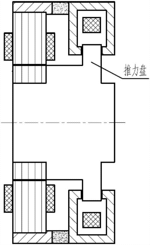
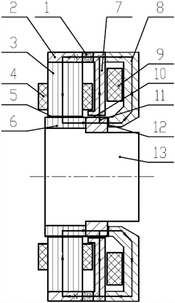
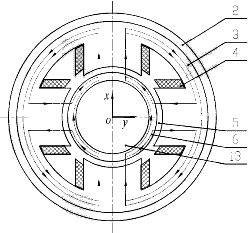
[0011] Such as figure 2 Shown, be the non-thrust disk diameter axial integrated permanent magnet bias magnetic bearing of the technical solution of the present invention, i.e. the basic form of the present invention, it is made up of 1 permanent magnet 1, 1 magnetic conduction ring 2, 1 diameter Stator core 3, 1 radial excitation coil 4, 1 radial rotor core 6, 1 ring pole 7, 1 axial stator core 8, 1 axial excitation coil 9, 1 magnetic thread ring 11 , 1 rotor shaft 13 is formed. The annular permanent magnet 1 is sandwiched between the magnetically permeable ring 2 and the annular magnetic pole 7 to provide a bias magnetic field for the magnetic bearing and isolate the radial and axial control magnetic fields to realize decoupling of the radial and axial control. A radial air gap 5 is formed between the radial stator core 3 and the rotor core 6, the permanent magnet bias flux and the axial control flux are conducted through the annular magnetic pole 7, and an annular air gap ...


PUM


Abstract

A non-thrust-disc radial and axial integrated permanent magnet biased magnetic bearing comprises a permanent magnet body, a magnetic conducting ring, a radial stator core, radial coils, a rotor core, an annular magnetic pole, an axial stator core, axial coils, a thread ring and a rotating shaft, wherein the permanent magnet is used for providing a biased magnetic field; biased magnetic flux and axial control magnetic flux are transferred through the annular magnetic pole; an annular air gap which is longer than a radial air gap is formed between the annular magnetic pole and the thread ring; the magnetic bearing generates force in a differential manner through four magnetic poles of a radial stator; the magnetic bearing is free of a thrust disc and generates force through the end surface of the thread ring; the thread ring is used for compressing the rotor core. An existing radial and axial integrated magnetic bearing axially generates forces through the thrust disc, thus the outside diameter of a rotor, the linear velocity and the ventilation losses are increased, and the mechanical safety margin and critical speed of rotation of the rotor are reduced. The non-thrust-disc radial and axial integrated permanent magnet biased magnetic bearing can solve the shortage of the existing radial and axial integrated magnetic bearing which axially generates force through the thrust disc; the non-thrust-disc radial and axial integrated permanent magnet biased magnetic bearing has the advantages of reducing the losses, and improving the mechanical safety margin and critical speed of rotation of the rotor.

Description

technical field [0001] The invention relates to a non-contact magnetic suspension bearing, in particular to a non-thrust disk radial and axial integrated permanent magnet bias magnetic bearing, which can be used as non-contact support for rotating parts in mechanical equipment such as motors and machine tools. Background technique [0002] The magnetic levitation technology applied to high-speed rotating machinery often requires good dynamic performance and high reliability of magnetic bearings. Especially when it is applied to rigid rotor high-speed rotating machinery, it also requires high first-order frequency of the rotor and low wind friction loss, such as blowers driven by magnetic levitation motors , compressors, and turbine generators for power generation systems. The traditional magnetic levitation system needs to configure two radial magnetic bearings and one axial magnetic bearing to constrain the five degrees of freedom of the rotor. In order to improve the dyna...

Claims


Application Information

Patent Timeline
Patent Type & Authority Patents(China)
IPC IPC(8): F16C32/04
CPCF16C32/0459
Inventor 韩邦成徐勤杰郑世强
Owner BEIHANG UNIV
Why Eureka
Try Eureka