Split torque transmission speed reduction device for helicopter

A technology of split torque transmission and deceleration device, which is applied in the direction of transmission device, gear transmission device, mechanical equipment, etc. It can solve the problems of unsuitable working conditions of large transmission ratio, uneven axial force of gears, and reduced service life, etc., and achieve quality Lightweight, low vibration and noise, and high survivability

Inactive Publication Date: 2017-04-26
NORTHWESTERN POLYTECHNICAL UNIV
View PDF7 Cites 3 Cited by
  • Summary
  • Abstract
  • Description
  • Claims
  • Application Information

AI Technical Summary

Problems solved by technology

[0004] Chinese patent CN101708774A "Helicopter main transmission system uses face gear and herringbone gear transmission combined shunt mechanism", on the basis of the AH-64M transmission system, the parallel level is changed to the herringbone gear meshing confluence, on the one hand to avoid the axial force of the gear The phenomenon of unevenness, on the other hand, the large overlap reduces the load of

Method used


Image

  • Split torque transmission speed reduction device for helicopter
  • Split torque transmission speed reduction device for helicopter

Examples


Embodiment 1

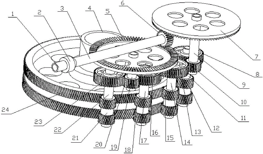
[0032] figure 1 For this example, the split-torque transmission reduction device of a helicopter with single engine input is adopted; wherein, the first engine output shaft 1 is connected with the first power input shaft 3 through the first overrunning clutch 2, and the first spur gear 6 is fixed at the second On a power input shaft 3, and meshes with the first face gear 5 and the second face gear 7 to realize steering, one-time split torque, and one-stage deceleration; the first face gear 5 and the second spur gear 20 pass through the first The double gear shaft 19 is connected, and the second face gear 7 is connected with the third spur gear 10 through the second double gear shaft 9; the third spur gear 10 is connected with the sixth spur gear 13 and the Seven spur gears 8 mesh with each other, and the second spur gear 20 meshes with the fourth spur gear 23 and the fifth spur gear 16 to realize two-stage deceleration and secondary torque splitting; the fourth spur gear The ...

Embodiment 2

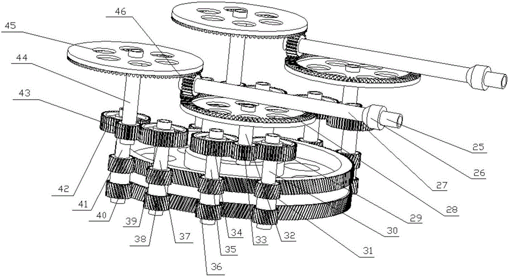
[0036] figure 2The split-torque transmission reduction gear of the helicopter that adopts twin-engine input for this example; Be to increase the second engine output shaft 25 on the basis of the split-torsion transmission reduction gear of the helicopter of single-engine input, the second overrunning clutch 26, the second power Input shaft 27, eighth spur gear 46, third face gear 28, fourth face gear 45, seventh double gear shaft 32, eighth double gear shaft 44, ninth spur gear 33, tenth spur gear 43, the tenth spur gear 29, the twelfth spur gear 34, the thirteenth spur gear 39, the fourteenth spur gear 42, the ninth double gear shaft 30, The tenth double gear shaft 35, the eleventh double gear shaft 37, the twelfth double gear shaft 41, the sixth herringbone cylindrical gear 31, the seventh herringbone cylindrical gear 36, and the eighth herringbone cylindrical gear Gear 38, the ninth herringbone spur gear 40. Wherein, power is input from the second input shaft 27, and the...


PUM


Abstract

The invention discloses a split torque transmission speed reduction device for a helicopter. Each engine input shaft is connected with a power input shaft through an overrunning clutch; a straight toothed spur gear on each power input shaft is engaged with two face gears installed in the opposite directions to achieve the power shunting, first-stage speed reduction and the reversing functions. The face gears are connected with the corresponding straight toothed spur gears through corresponding duplicate gear shafts and transmit power uniformly to the four straight toothed spur gears to achieve the second torque split and second-stage speed reduction functions. Power is transmitted to four herringbone toothed spur gears by the four straight toothed spur gears through the four duplicate gear shafts, and the four herringbone toothed spur gears are engaged with a fifth herringbone toothed spur gear correspondingly to achieve the second-stage speed reduction and parallel operation functions. The split torque transmission speed reduction device adopts multistage gear transmission, and is high in transmission ratio and low in vibration noise. Power is shunted through multiple branches. Torque transmitted by the gears in all the branches is reduced. The bearing capacity of the gears is improved. The fatigue life of the gears is prolonged. Accordingly, a transmission system has higher survivability.

Description

technical field [0001] The invention relates to the field of helicopter speed reducers, in particular to a split-torque transmission speed reduction device for helicopters. Background technique [0002] Since the helicopter came out, the transmission type of its reducer has been continuously improved. In the traditional helicopter reducer, the power of the engine is transmitted in a single way from input to output, and decelerates step by step; Stage planetary reduction output to the rotor shaft. But this traditional configuration is only suitable for the main reducer of light and small tonnage helicopters. Once the transmission power increases, the volume of the reducer will increase, the quality will increase, and the vibration and noise will also increase. This is not desired by the designer and the user, so the development and improvement of the helicopter reducer is imperative. [0003] The transmission system of the Apache helicopter prototype AH-64M adopts a spur g...

Claims


Application Information

Patent Timeline
IPC IPC(8): F16H1/22
CPCF16H1/222
Inventor 王三民黄雄袁茹郑维彤邢天倚裴安李浩颉晓欣
Owner NORTHWESTERN POLYTECHNICAL UNIV
Why Eureka
Try Eureka