
Digital speckle-based telecentric microscopic binocular stereoscopic vision measurement method

A technology of binocular stereo vision and digital speckle, which is applied in the direction of measuring devices, instruments, and optical devices, can solve the problems of small longitudinal measurement range, cumbersome measurement process, and small measurable range, and achieve low cost of measurement equipment, The effect of simple measurement process and fast measurement speed

Active Publication Date: 2017-04-26
HUAZHONG UNIV OF SCI & TECH
View PDF7 Cites 34 Cited by
  • Summary
  • Abstract
  • Description
  • Claims
  • Application Information

AI Technical Summary

Problems solved by technology

In the microscopic field, the three-dimensional measurement of microscopic digital speckle based on stereo microscope has problems such as fixed optical path, small longitudinal measurement range, and low measurement accuracy; while the combination of scanning electron microscope (SEM) and atomic force microscope (AFM) Microscopic digital speckle three-dimensional measurement requires measurement from multiple angles, expensive measurement equipment, cumbersome measurement process, and a small measurable range

Method used


Image

  • Digital speckle-based telecentric microscopic binocular stereoscopic vision measurement method
  • Digital speckle-based telecentric microscopic binocular stereoscopic vision measurement method

Examples


Embodiment Construction

[0024] In order to make the object, technical solution and advantages of the present invention clearer, the present invention will be further described in detail below in conjunction with the accompanying drawings and embodiments. It should be understood that the specific embodiments described here are only used to explain the present invention, not to limit the present invention. In addition, the technical features involved in the various embodiments of the present invention described below can be combined with each other as long as they do not constitute a conflict with each other.

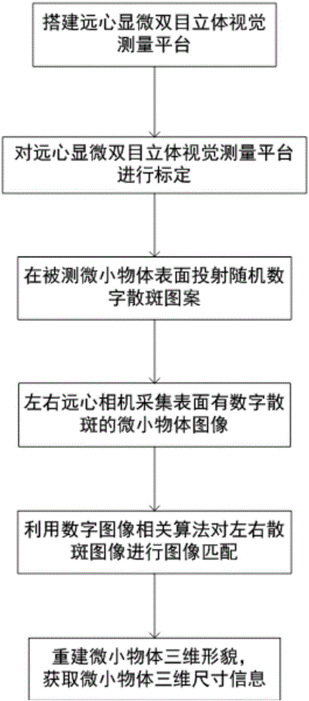
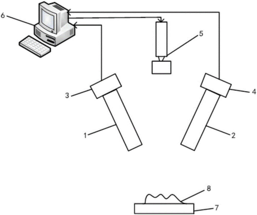
[0025] The invention discloses a telecentric microscopic binocular stereo vision measurement method based on digital speckle. On the basis of building a telecentric micro binocular stereo vision measurement platform and calibrating it, the digital speckle technology is introduced, through The left and right telecentric cameras collect images of tiny objects covered with speckle patterns, and per...


PUM


Abstract

The invention discloses a digital speckle-based telecentric microscopic binocular stereoscopic vision measurement method. The method includes the following steps that: 1) a telecentric microscopic binocular stereoscopic vision measurement platform is built; 2) the measurement platform is calibrated, the inner and outer parameters and relative position relations of a left telecentric camera and a right telecentric camera are determined; 3) a digital speckle pattern is projected onto the surface of a tiny object through a projector; 4) the left telecentric camera and the right telecentric camera are utilized to simultaneously shoot the to-be-measured tiny object of which the surface is covered with the digital speckle pattern, and a left speckle pattern and a right speckle pattern are acquired; 5) image matching is performed on the left speckle pattern and the right speckle pattern, matching relations of corresponding points in the left speckle pattern and the right speckle pattern are obtained, and the three-dimensional point cloud data of the tiny object are obtained according to the inner and outer parameters and relative position relations of the left telecentric camera and the right telecentric camera; and 6) the three-dimensional form of the tiny object is reconstructed according to the three-dimensional point cloud data, and the three-dimensional size information of the to-be-measured tiny object is obtained. The digital speckle-based telecentric microscopic binocular stereoscopic vision measurement method has the advantages of fast measurement speed, high measurement precision and the like.

Description

technical field [0001] The invention belongs to the field of stereo vision measurement, and more specifically relates to a telecentric microscopic binocular stereo vision measurement method based on digital speckle. Background technique [0002] As a non-contact measurement method, binocular stereo vision technology is widely used in three-dimensional measurement of object size. At present, the technology is mainly divided into two categories: traditional passive binocular stereo vision measurement and active binocular stereo vision measurement based on structured light. Passive binocular stereo vision measurement technology obtains the 3D coordinate value of the same 3D space point based on the parallax in the images taken by two cameras at different spatial positions and the spatial geometric relationship between the cameras, and then obtains A three-dimensional measurement of the size of an object. Active binocular stereo vision measurement technology actively creates f...

Claims


Application Information

Patent Timeline
IPC IPC(8): G01B11/25G01B11/00
CPCG01B11/002G01B11/254G01B11/2545
Inventor 廖广兰陈科鹏史铁林王西彬汤自荣张贻春洪源王肖
Owner HUAZHONG UNIV OF SCI & TECH
Learn More