
Method for determining critical buckling load of deck longitudinal beam column supported by cantilever cross beam

A critical load and determination method technology, applied in the field of ship structure engineering, can solve problems such as high requirements, large modeling and calculation time, low calculation accuracy and low efficiency of hull girder residual strength, and achieves high adaptability and a wide range of considerations. , the effect of improving efficiency and accuracy

Active Publication Date: 2017-04-26
708TH RES INST OF CSSC
View PDF1 Cites 7 Cited by
  • Summary
  • Abstract
  • Description
  • Claims
  • Application Information

AI Technical Summary

Problems solved by technology

However, the nonlinear finite element method has high requirements for computer and software operators, and it takes a lot of modeling and calculation time, and it is impossible to obtain the stability calculation formula and large-scale damage of the hull plate frame longitudinal with large-scale collision damage Influence Law of Ultimate Strength of Plate Frame
It causes inconvenience to the design and performance evaluation of the hull structure, and the calculation accuracy and efficiency of the remaining strength of the hull girder are low, which affects the quality and accuracy of the ship design

Method used


Image

  • Method for determining critical buckling load of deck longitudinal beam column supported by cantilever cross beam
  • Method for determining critical buckling load of deck longitudinal beam column supported by cantilever cross beam
  • Method for determining critical buckling load of deck longitudinal beam column supported by cantilever cross beam

Examples


Embodiment Construction

[0032] In order to make it easy to understand the technical means, creative features, goals and effects achieved by the present invention, the following examples are combined with the appended figure 1 to attach Figure 8 The technical solutions provided by the present invention are described in detail, but the following content is not intended as a limitation of the present invention.

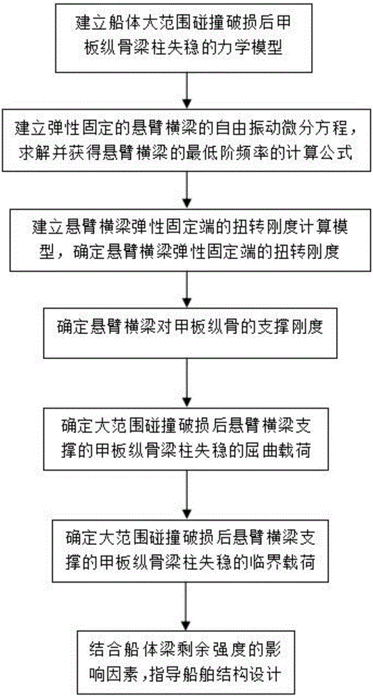
[0033] The invention is a method for determining the buckling critical load of a longitudinal beam-column supported by a cantilever beam. figure 1 It is a flow chart of an embodiment of a method for determining the buckling critical load of a longitudinal beam-column supported by a cantilever beam in the present invention. like figure 1 As shown, the method for determining the buckling critical load of a longitudinal beam-column supported by a cantilever beam provided in this embodiment includes the following steps:

[0034] The first step is to establish the calculation model of the buckli...


PUM


Abstract

The invention provides a method for determining the critical buckling load of a deck longitudinal beam column supported by a cantilever cross beam, and belongs to the technical field of ship structure engineering. The method includes the following steps: 1. establishing a deck longitudinal beam unstability mechanics model; 2. establishing a cantilever cross beam mechanics equation, and determining a fundamental frequency calculation formula: 3. establishing a cantilever cross beam fixed end torsional rigidity calculation model, and determining torsional rigidity; 4. determining supporting rigidity of the cantilever cross beam to the deck longitudinal beam; 5. determining the buckling load of the deck longitudinal beam column which is supported by the cantilever cross beam; 6. obtaining the critical buckling load of the deck longitudinal beam column supported by the cantilever cross beam; and 7. in combination with a ship girder residual rigidity impact factor, guiding the design of a ship structure. According to the invention, the method can rapidly determine large-range collision and damage and the critical buckling load of the deck longitudinal beam column, reveals the pattern of how the ultimate strength of a grillage of the deck is affected, and guides the design of residual strength of the ship body.

Description

technical field [0001] The invention relates to the technical field of ship structural engineering, in particular to a method for determining the buckling critical load of a deck longitudinal beam column supported by a cantilever beam. Background technique [0002] Accurate calculation and reasonable evaluation of the damaged residual strength of the hull can effectively ensure the rationality and safety of the ship structure design. Determining the buckling load of the deck longitudinal beams and columns supported by the cantilever beam is the key to determining the ultimate strength of the damaged hull girder. [0003] The International Association of Classification Societies (IACS) added the content of residual strength check after hull girder damage to the HCSR code implemented in 2016. HCSR stipulates the depth and height of the damage extent of the collision for the calculation of the surviving ultimate strength of bulk carriers and oil tankers. However, since the len...

Claims


Application Information

Patent Timeline
IPC IPC(8): G01M7/08G01M5/00
CPCG01M5/0075G01M7/08
Inventor 万琪贺远松王福花吴剑国马剑
Owner 708TH RES INST OF CSSC
Learn More