A metering system and method with self-provided power supply user Π access system

A self-provided power supply and access system technology, applied in the direction of special billing meters, etc., can solve the problems that cannot be clarified, and the measurement method cannot adapt to the settlement requirements of the power grid and the exchanged electricity of enterprises, so as to achieve flexible solutions, good economic benefits and Effects of social benefits, investment saving and land occupation

Active Publication Date: 2019-03-22
STATE GRID CORP OF CHINA +1
View PDF10 Cites 0 Cited by
  • Summary
  • Abstract
  • Description
  • Claims
  • Application Information

AI Technical Summary

Problems solved by technology

[0005] (2) Since the switch station of the enterprise is connected to two substations of the power grid, there may be power through the switch station of the enterprise
[0009] However, if the power flow of the enterprise and the power grid has both figure 2 , image 3 As shown, there are also Figure 4 In the situation shown, using the two gateway meters A and B will not be able to clarify the off-grid electricity supplied by the grid to the enterprise and the on-grid electricity provided to the grid by the surplus electricity generated by the enterprise for self-use within a measurement period. Different, so the conventional measurement method will not be able to meet the settlement requirements of the electricity exchange between the power grid and the enterprise, so it is necessary to study the measurement method of this access system, and propose a measurement method that meets the exchange of electricity settlement between the power grid company and the enterprise

Method used


Image

  • A metering system and method with self-provided power supply user Π access system
  • A metering system and method with self-provided power supply user Π access system
  • A metering system and method with self-provided power supply user Π access system

Examples


Embodiment Construction

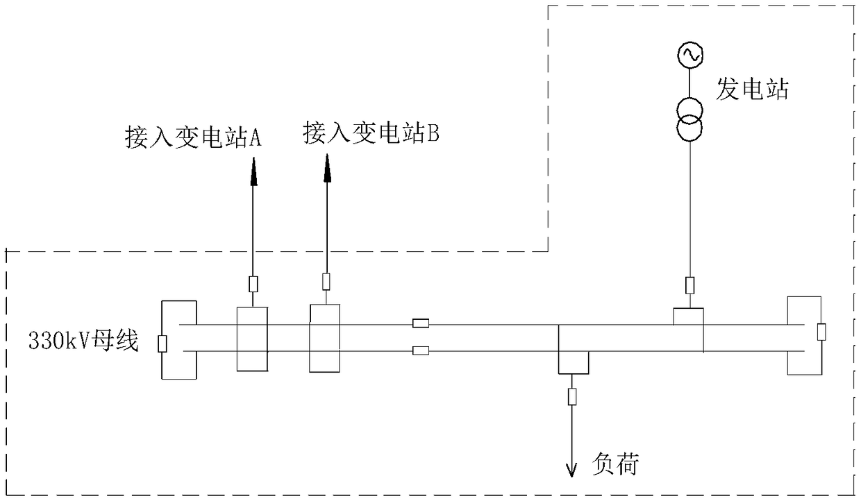
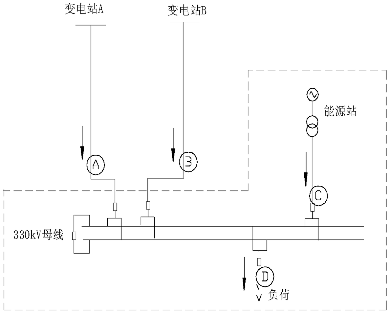
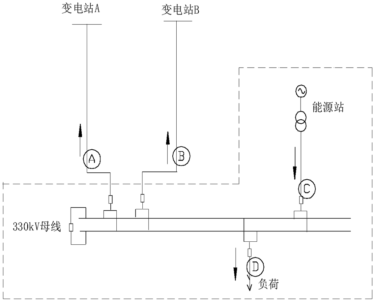
[0024] see figure 1 As shown, the metering system of the present invention has a self-contained power supply user Π access system, including a user switching station, a user-provided power supply, a power grid substation A, a power grid substation B, a current transformer CT1, a current transformer CT2, and an electrical degree surface.

[0025] The user switch station is connected to user load, user-owned power supply, grid substation A and grid substation B, CT1 is used to monitor the current between the switch station and grid substation A, and CT2 is used to monitor the current between the switch station and grid substation B; The current loop of the watt-hour meter is the sum of the currents connected to the secondary side metering windings of CT1 and CT2, and the voltage loop of the watt-hour meter is connected to the user switching station and the grid substation A or the user switching station and the grid substation B. Any line PT secondary side voltage.

[0026] Th...


PUM


Abstract

The invention discloses a metering system and method having a self-contained power supply user pi access system. The metering system includes a user switching station, a user self-contained power supply, a power grid transformer station A, a power grid transformer station B, a CT1, a CT2 and an electric meter; the user switching station is connected with the self-contained power supply, the power grid transformer station A and the power grid transformer station B, the CT1 is used for monitoring current between the switching station and the power grid transformer station A, and the CT2 is used for monitoring current between the switching station and the power grid transformer station B; a current loop of the electric meter adopts access of secondary sides of CT1 and CT2 to meter a current sum of winding outgoing lines, a voltage loop of the electric meter adopts access of secondary side voltage of a voltage transformer of any one of two loops of the user switching station and the power grid transformer station A or the user switching station and the power grid transformer station B. The metering system and method having the self-contained power supply user pi access system solves the problem of metering of large users having self-owned power plants of a pi access power grid, and can enable a one-time access scheme to be flexible and simple, thereby saving investment and occupied area, and achieving very good economic benefits and social benefits.

Description

technical field [0001] The invention relates to the technical field of electricity metering, in particular to a metering system and method with a self-provided power supply user Π access system, and the user's on-grid electricity charges and off-grid electricity charges are different. Background technique [0002] see figure 1 As shown, when an enterprise "∏" with self-provided power plant is connected to the power grid, since the access points are respectively connected to the two substations of the power grid, both the load and the power supply are connected to the switch station of the enterprise, so At the access point, there may be cross-over power between two substations of the system, off-grid power supplied by the system to the enterprise, and on-grid power of the enterprise's power station for self-use surplus power to the system. [0003] The power flow of power grids and enterprise switching stations has the following characteristics: [0004] (1) The switch sta...

Claims


Application Information

Patent Timeline
Patent Type & Authority Patents(China)
IPC IPC(8): G01R11/57
CPCG01R11/57
Inventor 戴立森王新何晓英安尤晨杨晓西宋晓林孙宏丽王若谷董拓罗威张飞
Owner STATE GRID CORP OF CHINA
Why Eureka
Try Eureka