Thick oil thermal extraction saturated steam flow metering method

A heavy oil thermal recovery and steam flow technology, which is applied in the fields of fluid production, measurement, earthwork drilling and production, etc., can solve the problems of not meeting the measurement conditions and requirements, not being able to calculate the flow rate of a single well, and the large steam flow rate. Simple, easy-to-use, reliable results

Inactive Publication Date: 2012-08-22
LIAOHE GASOLINEEUM EXPLORATION BUREAU
View PDF5 Cites 0 Cited by
  • Summary
  • Abstract
  • Description
  • Claims
  • Application Information

AI Technical Summary

Problems solved by technology

[0003] The purpose of the present invention is to provide a method for measuring the flow rate of saturated steam in heavy oil thermal recovery wells, which solves the problem that the existing metering instruments in the prior art cannot meet the metering conditions and metering requirements of 350°C, 17MPa high-temperature and high-pressure saturated steam , the existing metering method cannot calculate the flow rate of a single well; the steam flow rate of a single well is relatively large when the steam injection temperature and pressure of the wellhead are converted according to the number of boiler steam injection wells

Method used


Image

  • Thick oil thermal extraction saturated steam flow metering method
  • Thick oil thermal extraction saturated steam flow metering method

Examples


Embodiment Construction

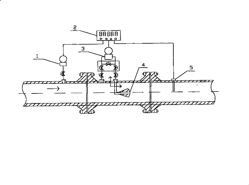
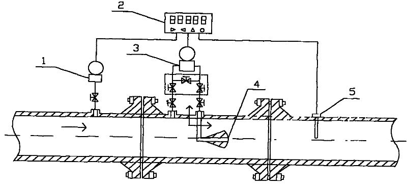
[0009] The heavy oil thermal recovery well saturated steam flow measurement method is realized by the heavy oil thermal recovery well saturated steam flowmeter. In the attached drawing, the heavy oil thermal recovery well saturated steam flowmeter is composed of pressure sensor 1, display Transmitter 3, V-shaped cone 4, and temperature sensor 5 are composed of: pressure sensor 1 is threadedly connected to the front section of the metering pipeline, display 2 is threaded with pressure sensor 1, differential pressure transmitter 3, and temperature sensor 5, and V-shaped cone The body 4 is welded to the differential pressure transmitter 3; the V-shaped cone 4 is a new V-shaped inner cone structure, which determines the measurement range.

[0010] The method is to connect the saturated steam flow meter of the heavy oil thermal recovery well with the two ends of the manifold to the steam injection well. pressure to realize the accurate measurement of the flow rate of saturated stea...


PUM


Abstract

The invention relates to a thick oil thermal production well saturated steam flow metering method for thick oil thermal production steam drive steam-injection well high-temperature high-pressure saturated steam individual well metering, which is realized by a thick oil thermal production well saturated steam flow meter. The thick oil thermal production well saturated steam flow meter comprises a pressure sensor, a display, a differential pressure transmission, a V-shaped cone and a temperature sensor, wherein the pressure sensor is connected with a metering pipeline thread, the display is connected with the pressure sensor, the differential pressure transmission and a temperature sensor thread in a welding way, and the V-shaped cone is connected with the differential pressure transmissionin a welding way. In the method, the thick oil thermal production well saturated steam flow meter is in threaded connection with a steam-injection well, differential pressure is generated from both ends of the V-shaped cone when steam passes through the thick oil thermal production well saturated steam flow meter, thus the thick oil thermal production well saturated steam flow metering method realizes the accurate measurement of saturated steam flow speed; the differential pressure transmission converts the saturated steam flow speed into flow signals and sends the flow signals to a computer system to display steam individual well metering at any time; and the thick oil thermal production well saturated steam flow metering method solves the problem that individual well flow can not be metered in the prior art and can be used for the thick oil thermal production steam drive steam-injection well high-temperature high-pressure saturated steam individual well metering.

Description

Technical field: [0001] The invention relates to a heavy oil thermal recovery well saturated steam flow metering method for single well measurement of high temperature and high pressure saturated steam in heavy oil thermal recovery steam drive oil recovery, horizontal wells and steam injection wells. Background technique: [0002] Currently Liaohe Oilfield heavy oil thermal recovery technology. It has developed from single well steam huff and puff to steam flooding oil recovery and horizontal well recovery technology. The development of oil recovery technology and the expansion of production scale require corresponding technical support. At present, the existing measuring instruments at home and abroad cannot meet the measurement conditions and requirements of 350°C, 17MPa high-temperature and high-pressure saturated steam. The steam displacement of the imported steam injection boiler is not measured, and the steam flow at the filter outlet is the steam dryness obtained fro...

Claims


Application Information

Patent Timeline
Patent Type & Authority Patents(China)
IPC IPC(8): E21B47/00E21B43/24
Inventor 马明周志军宋启辉刘胜杰刘付臣曾魏张涛黄昌义张健杨峰王风岩
Owner LIAOHE GASOLINEEUM EXPLORATION BUREAU
Why Eureka
Try Eureka