
Sound detection and positioning system

A positioning system and sound detection technology, applied in the field of sound sensing, can solve the problems that the positioning accuracy is easily affected by the environment, is not suitable for miniaturization, and is not easy to carry, and achieves the effects of improving the sound positioning accuracy, compact structure and flexible use.

Active Publication Date: 2017-04-26
INST OF ELECTRONICS CHINESE ACAD OF SCI
View PDF5 Cites 0 Cited by
  • Summary
  • Abstract
  • Description
  • Claims
  • Application Information

AI Technical Summary

Problems solved by technology

[0007] In view of the above technical problems, the present invention provides an acoustic detection and positioning system based on an acoustic waveguide array to overcome the large volume, heavy weight, inconvenient portability, unsuitable miniaturization and positioning accuracy of existing bracket-type acoustic detection and positioning devices. Disadvantages such as being susceptible to environmental influences

Method used


Image

  • Sound detection and positioning system
  • Sound detection and positioning system
  • Sound detection and positioning system

Examples


no. 1 example

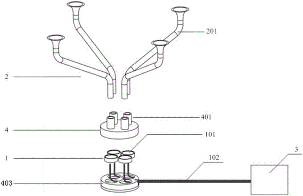
[0030] In a first exemplary embodiment of the present invention, an acoustic detection and location system is provided. figure 1 It is a schematic diagram of the structural decomposition of the sound detection and positioning system in the first embodiment of the present invention, please refer to figure 1 , an acoustic detection and positioning system, comprising: an acoustic sensor array 1 , an acoustic waveguide array 2 , a signal processing chip 3 , and a connector 4 .

[0031] The acoustic sensor array 1 includes N acoustic sensing units 101 , where N≧2, and the acoustic sensing units may be discrete acoustic sensors or integrated on a chip.

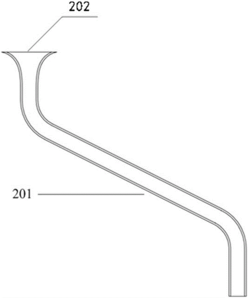
[0032] The acoustic waveguide array 2 includes M acoustic waveguides 201, wherein M≥2, each acoustic waveguide is in the shape of a circular tube with two ends open and connected, one end of which is connected to the corresponding acoustic sensing unit 101, and the other end is placed in the air. The ends of all the acoustic wavegu...

no. 1 example 1

[0045] So far, the introduction of the acoustic detection and positioning system according to the first embodiment of the present invention is completed.

no. 2 example

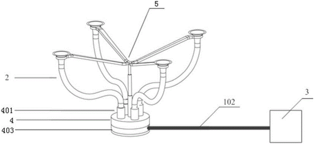
[0047] In a second exemplary embodiment of the present invention, an acoustic detection and location system is provided. figure 2 It is a schematic diagram of the acoustic detection and positioning system in the second embodiment of the present invention. Such as figure 2 As shown, compared with the acoustic detection and positioning system of the first embodiment, the difference of the acoustic detection and positioning system of this embodiment is:

[0048] The acoustic waveguide 201 is a flexible conduit, and the flexible conduit may be one of a plastic conduit, a rubber conduit, a silicone rubber conduit, and a polytetrafluoroethylene conduit;

[0049] The acoustic waveguide array also includes a bracket 5 for fixing one end of the flexible conduit placed in the air. Specifically, the bracket is a rigid, foldable bracket.


PUM


Abstract

The invention provides a sound detection and positioning system, and the system comprises a sound sensor array and a sound wave conduit array, wherein the sound sensor array comprises N sound sensor units, and N is not less than two. The sound wave conduit array comprises M sound wave conduits, wherein M is not less than two. Two ends of each sound wave conduit are opened and connected and are shaped like a circular pipe, wherein one end of each sound wave conduit is connected with the corresponding sound sensor unit, and the other end of each sound wave conduit is disposed in the air. A sound signal transmitting in the air enters into the sound wave conduits of the sound wave conduit array, and then is received by the sound sensor units of the sound sensor array. The system is small in size, is light in weight, and is portable. The sound sensor array is compact in structure, and difference on the sound sensor units from an external environment is small. The measurement accuracy of the system is high.

Description

technical field [0001] The invention relates to the technical field of acoustic sensing, in particular to an acoustic detection and positioning system based on an acoustic waveguide array. Background technique [0002] Acoustic detection and positioning technology involves multiple disciplines and technologies such as acoustics, electronics, sensor technology, signal processing technology, and computer algorithms. It is a typical multidisciplinary and highly cross-integrated technology. Acoustic detection and positioning technology has important applications in many fields such as environment, medical treatment, industry, transportation, military affairs, etc., and has received great attention and extensive research at home and abroad. [0003] Acoustic detection and positioning technology is divided into two types: active and passive. Common ultrasonic nondestructive testing and ultrasonic imaging diagnosis popularized in hospitals belong to active acoustic detection and po...

Claims


Application Information

Patent Timeline
IPC IPC(8): G01S15/06G01S7/523G01S7/534
CPCG01S7/523G01S7/534G01S15/06
Inventor 祁志美程进高然逯丹凤
Owner INST OF ELECTRONICS CHINESE ACAD OF SCI
Learn More