Heat dissipation apparatus and electronic device
A technology for heat dissipation devices and electronic equipment, applied in the fields of electrical digital data processing, instruments, calculations, etc., can solve problems such as undeveloped technical solutions, achieve the effect of improving heat dissipation efficiency and realizing heat recovery
- Summary
- Abstract
- Description
- Claims
- Application Information
AI Technical Summary
Problems solved by technology
Method used
Image

Examples
Embodiment 1
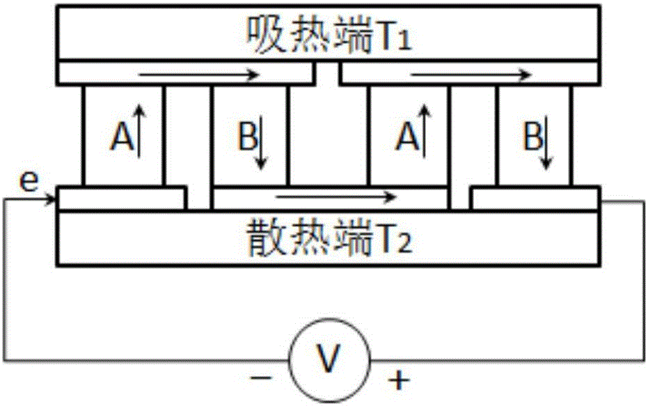
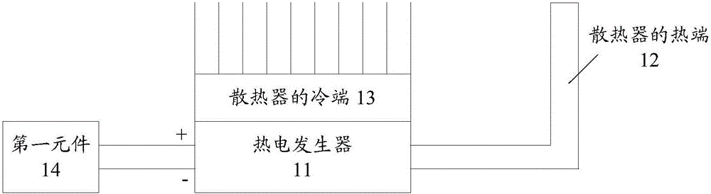
[0031] An embodiment of the present invention provides a heat dissipation device. image 3 It is a schematic diagram of the first composition and structure of the heat dissipation device of the embodiment of the present invention; image 3 As shown, the heat dissipation device includes: a thermoelectric generator 11, a heat sink and a first element 14; the heat sink includes a cold end 13 and a hot end 12; the first end of the thermoelectric generator 11 and the heat sink The hot end 12 of the heat sink is bonded and connected to absorb the heat of the hot end 12 of the heat sink; the second end of the thermoelectric generator 11 is bonded to the cold end 13 of the heat sink, so that the second end forming a temperature difference between the end and the first end;
[0032] The thermoelectric generator 11 is used to convert the temperature difference formed between the first end and the second end into a voltage, and output the voltage to the first element 14, so that the fir...
Embodiment 2
[0039] The embodiment of the invention also provides a heat dissipation device. Figure 4It is a schematic diagram of the second composition and structure of the heat dissipation device of the embodiment of the present invention; Figure 4 As shown, the heat dissipation device includes: a thermoelectric generator 11, a heat sink and a first element 14; the heat sink includes a cold end and a hot end; the first end of the thermoelectric generator 11 and the heat sink of the heat sink The end 12 is bonded and connected to absorb the heat of the hot end 12 of the heat sink; the second end of the thermoelectric generator 11 is bonded to the cold end 13 of the heat sink, so that the second end and the cold end 13 of the heat sink are bonded. forming a temperature difference at the first end;
[0040] The thermoelectric generator 11 is used to convert the temperature difference formed between the first end and the second end into a voltage, and output the voltage to the first eleme...
Embodiment 3
[0047] The embodiment of the present invention also provides an electronic device. Figure 5 It is a schematic diagram of the first composition and structure of the electronic device according to the embodiment of the present invention; Figure 5 As shown, the electronic equipment includes a heat sink; the heat sink includes: a thermoelectric generator 21, a heat sink and a first element; the heat sink includes a cold end and a hot end; the first end of the thermoelectric generator 21 Fitted and connected with the hot end 22 of the radiator, for absorbing the heat of the hot end 22 of the radiator; the second end of the thermoelectric generator 21 is bonded with the cold end 23 of the radiator, so as to forming a temperature differential between the second end and the first end;
[0048] The thermoelectric generator 21 is used to convert the temperature difference formed between the first end and the second end into a voltage, and output the voltage to the first element, so t...
PUM
 Abstract
Description
Claims
Application Information
 - R&D
- Intellectual Property
- Life Sciences
- Materials
- Tech Scout
- Unparalleled Data Quality
- Higher Quality Content
- 60% Fewer Hallucinations
Browse by: Latest US Patents, China's latest patents, Technical Efficacy Thesaurus, Application Domain, Technology Topic, Popular Technical Reports.
© 2025 PatSnap. All rights reserved.Legal|Privacy policy|Modern Slavery Act Transparency Statement|Sitemap|About US| Contact US: help@patsnap.com