
Membrane type dew point indirect evaporative cooling heat exchanger

A technology of dew point evaporative cooling and heat exchanger, which is applied in the direction of indirect heat exchanger, heat exchanger type, lighting and heating equipment, etc. Complex structure and other issues to achieve the effect of balance and controllability, low production cost and high degree of automation

Pending Publication Date: 2018-01-05
陈祖卫
View PDF0 Cites 1 Cited by
  • Summary
  • Abstract
  • Description
  • Claims
  • Application Information

AI Technical Summary

Problems solved by technology

[0006] Aiming at many defects and deficiencies existing in the prior art, such as excessive resistance of the external shunt hole, uneven temperature field, complex structure of the heat exchanger, and difficulty in meeting the requirements of heat exchange efficiency, the present invention proposes a diaphragm type dew point indirect The evaporative cooling heat exchanger, by improving the cross-sectional structure of the dry-wet heat exchange channel and setting an asymmetric dry-wet heat exchange channel, can realize the mixing of counterflow and cross flow, and reduce the flow pressure drop while ensuring a small heat exchange temperature difference. Improve heat transfer efficiency

Method used


Image

  • Membrane type dew point indirect evaporative cooling heat exchanger
  • Membrane type dew point indirect evaporative cooling heat exchanger
  • Membrane type dew point indirect evaporative cooling heat exchanger

Examples


Embodiment 1

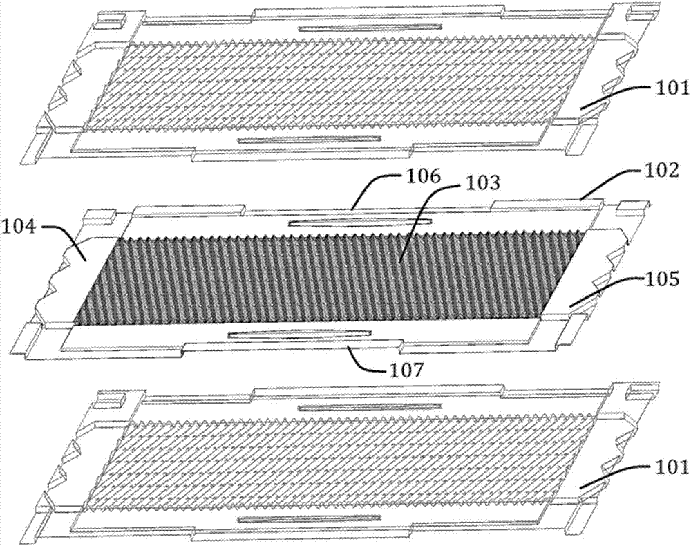
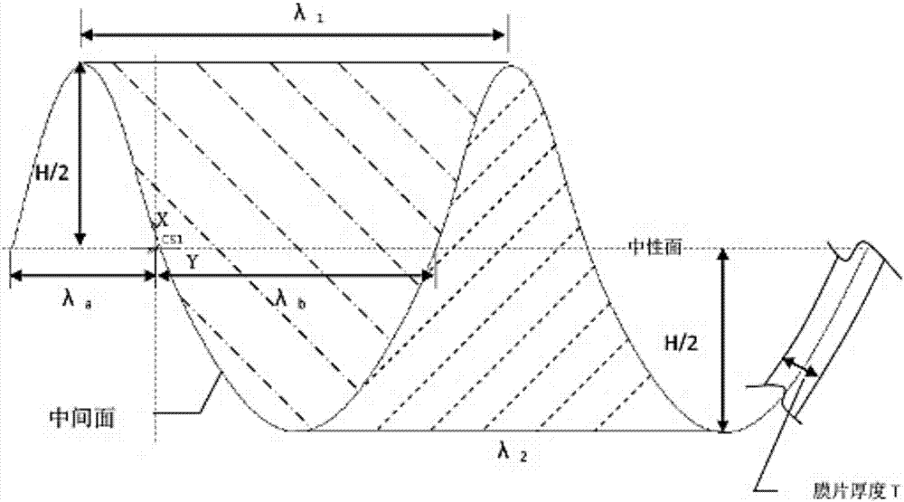
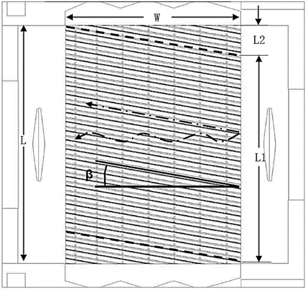
[0040] Such as figure 1 , Image 6 with Figure 7 As shown, the present embodiment is provided with alternately stacked first heat exchange membranes 101 and second heat exchange membranes 102; one side of the second heat exchange membranes 102 is a hydrophilic surface, and the other side is a hydrophobic surface , including: the central corrugated heat exchange area 103 and the first folded cavity surface 104 and the second folded cavity surface 105 arranged on both sides of the corrugated heat exchange area 103; the first heat exchange film 101 and the second heat exchange film The sheets 102 have the same structure and are centrally symmetrical, that is, the first heat exchange membrane 101 is rotated 180° by the second heat exchange membrane 102, the first folding cavity surface 104 on the first heat exchange membrane 101 and the second folding cavity Surfaces 105 respectively correspond to the second folded cavity surface 105 and the first folded cavity surface 104 on t...

Embodiment 2

[0072] Such as Figure 11 As shown, the first heat exchange membrane 101 and the second heat exchange membrane 102 constituting the heat exchanger in this embodiment are designed with no static pressure chamber and inlet and outlet flow guide structures, which can be used in heat exchangers under single cooling conditions , small size, less consumables.

[0073] Such as Figure 10 with Figure 11 As shown, this embodiment includes alternately stacked first heat exchange membranes 101 and second heat exchange membranes 102, wherein: the hydrophilic surface of the first heat exchange membrane 101 and the hydrophilic surface of the second heat exchange membrane 102 The faces are oppositely arranged to form a wet heat exchange channel layer, and the hydrophobic surface of the first heat exchange membrane 101 is arranged opposite to the hydrophobic surface of the second heat exchange membrane 102 to form a dry heat exchange channel layer; the first fold cavity surface 104 and the...


PUM


Abstract

The invention discloses a membrane type dew point evaporative cooling heat exchanger in the technical field of heat exchangers. The membrane type dew point evaporative cooling heat exchanger is internally provided with first heat exchanging membranes and second heat exchanging membranes all of which are overlapped in an alternate manner, wherein a hydrophilic face of each first heat exchanging membrane and a hydrophilic face of the corresponding second heat exchanging membrane are oppositely arranged to form a wet heat exchanging channel layer, and a hydrophobic face of each first heat exchanging membrane and a hydrophobic face of the corresponding second heat exchanging membrane are oppositely arranged to form a dry heat exchanging channel layer; and a first foldable cavity face and a second foldable cavity face are combined at the semi-opening ends of the wet heat exchanging channel layers to form a water inlet and outlet cavity and are closed at the dry heat exchanging channel layers. By means of the membrane type dew point indirect evaporative cooling heat exchanger, mixing of countercurrent and cross-flow can be achieved, meanwhile, by improving cross section structures of thedry heat exchanging channels and the wet heat exchanging channels, while the relative small heat exchanging temperature difference is guaranteed, the flowing pressure drop is reduced, and the heat exchanging efficiency is improved.

Description

technical field [0001] The invention relates to a technology in the field of heat exchangers, in particular to a membrane-type dew point indirect evaporative cooling heat exchanger. Background technique [0002] The dew point indirect evaporative cooling system obtains cooling capacity through heat and moisture exchange between water and air, and can provide air close to the dew point. It has the advantages of simple structure, few moving parts, and high energy efficiency ratio. However, the dew point indirect evaporative heat exchanger Heat transfer efficiency and higher manufacturing cost compared to direct evaporative heat exchangers are important factors that hinder the widespread use of this system. [0003] At present, most dew point indirect evaporative heat exchangers are of plate-fin structure, including: longitudinal dry air channels and horizontal wet air channels; by setting small air holes in the middle of the longitudinal dry air channels, the air flowing throu...

Claims


Application Information

Patent Timeline
Patent Type & Authority Applications(China)
IPC IPC(8): F28D9/02
Inventor 陈祖卫
Owner 陈祖卫
Learn More