Heat exchange method and structure for fluid and heat recovery system for waste water

A heat exchange structure and heat method technology, applied in the field of heat exchange, can solve the problems of ineffective heat exchange, fouling of corrugated grooves, affecting heat exchange efficiency, etc., and achieve the effect of energy saving

Pending Publication Date: 2022-05-27
宁波锦心节能环保科技有限公司
View PDF1 Cites 1 Cited by
  • Summary
  • Abstract
  • Description
  • Claims
  • Application Information

AI Technical Summary

Problems solved by technology

[0005] The above-mentioned patent uses corrugated pipes to manufacture heat recovery pipes. Although it can strengthen the turbulent flow of waste water, it is easy to cause fouling in the grooves of the corrugated pipes, thereby affecting the heat exchange efficiency; although a compressed air pipe is installed as a cleaning device, for For dense corrugated grooves, it cannot effectively ensure that each groove can be cleaned in place
At the same time, the above-mentioned patent uses the method of soaking the heat recovery pipe in the sewage pipe to realize heat exchange. The heat recovery pipe is arranged as a spiral pipe to extend the heat exchange stroke, but the linear motion of the sewage has a limited stroke, which is in the The sewage at the axis passes through the heat recovery pipe in an instant, and no effective heat exchange is obtained

Method used


Image

  • Heat exchange method and structure for fluid and heat recovery system for waste water
  • Heat exchange method and structure for fluid and heat recovery system for waste water
  • Heat exchange method and structure for fluid and heat recovery system for waste water

Examples


Embodiment 1

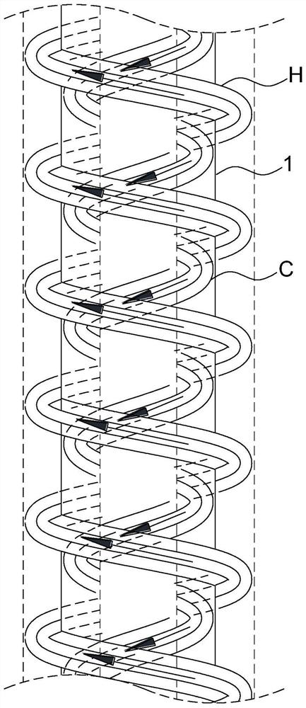
[0041] Embodiment 1 of the present application provides a heat exchange method for fluids, please refer to image 3 , specifically includes: heat exchange partition 1, cold flow C and heat flow H are separated by heat exchange partition 1, and heat exchange partition 1 is a thin-walled cylindrical structure extending axially; cold flow C and heat flow H, one of which is along the axis of the cylinder While rising up, it continues to rotate around the axis of the cylinder, while the other continues to rotate around the axis of the cylinder while going down the axis of the cylinder, and heat exchange is achieved through the heat exchange partition 1 .

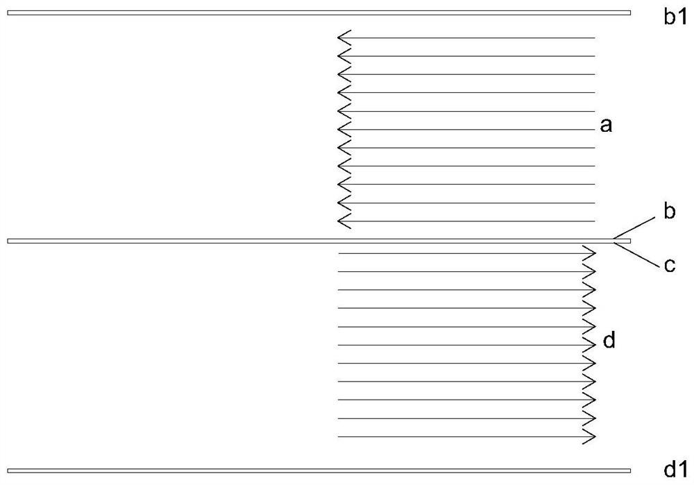
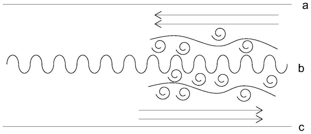
[0042] The technical solution of the present application makes the cold flow C and the heat flow H do reverse spiral convection motion. Compared with the simple linear reverse convection heat transfer method, the heat exchange efficiency is significantly improved; on the other hand, compared with the linear convection heat transf...

Embodiment 2

[0051] Embodiment 2 of the present application provides a heat exchange structure for fluids, please refer to Figure 5 , including the heat exchange partition wall 2, the heat exchange partition wall 2 has an axially extending thin-walled cylindrical structure, the first flow channel 2a and the second flow channel 2b separated by the heat exchange partition wall 2, the cold flow and the heat flow, one of which is in the first flow channel. 2a spirally rises along the axial direction of the cylinder, and the other spirals downward along the axial direction of the cylinder in the second flow channel 2b, and the heat exchange is realized through the heat exchange partition 2 .

[0052] It should be noted that the heat exchange partition wall 2 can be a thin-walled cylinder, or it can be an elliptical column, prism and other axially extending structural forms extending in the axial direction. The cross-sectional dimension of the heat exchange partition wall 1 can be along the axis...

Embodiment 3

[0065] Embodiment 3 of the present application provides a waste water heat recovery system, please refer to Image 6 , including a heat exchanger 14, wherein the heat exchanger 14 adopts the heat exchange structure described in Embodiment 2.

[0066] The waste water, as a hot flow, is introduced into the first fluid inlet 7 by the flow control device 22 through the pipeline 13, spirals up rapidly in the first flow channel 2a, and then exits through the first fluid outlet 5, and the cold flow enters through the second fluid inlet 4 , spiral downward in the second flow channel 2b, and pass out from the second fluid outlet 6, use the waste heat of the waste water to heat the cold flow, and realize the waste heat recovery of the waste water.

[0067] In some possible implementations, the waste water heat recovery system of this embodiment further includes a fouling cleaning device.

[0068] Illustratively, see Image 6 , the dirt cleaning device may include a cleaning agent storag...


PUM


Abstract

The invention relates to the technical field of heat exchange, in particular to a heat exchange method and structure for fluid and a heat recovery system for waste water. The heat exchange method is characterized in that cold flow and heat flow are separated through a heat exchange dividing wall, the heat exchange dividing wall is of a thin-wall cylinder-shaped structure extending in the axial direction, one of the cold flow and the heat flow continuously rotates around the axis of a cylinder while rising in the axial direction of the cylinder on the inner side of the heat exchange dividing wall, and the other one of the cold flow and the heat flow continuously rotates around the axis of the cylinder while rising in the axial direction of the cylinder. And the other one continuously rotates around the axis of the column body while descending along the axial direction of the column body on the outer side of the heat exchange dividing wall, and exchanges heat through the heat exchange dividing wall. Cold flow and hot flow strengthen heat exchange through reverse convection, and meanwhile two effects are generated through rotating motion, one effect is that the flowing direction of fluid is continuously changed in the circumferential direction, so that turbulent flow is generated, and the heat exchange efficiency is improved; and secondly, the heat exchange stroke of the fluid is prolonged, so that the heat exchange effect is further improved.

Description

technical field [0001] The invention relates to the technical field of heat exchange, in particular to a heat exchange method and structure for fluid and a heat recovery system for waste water. Background technique [0002] The problem of heat recovery of wastewater has always been a technical content that has been widely concerned. For example, the discharge temperature of bathing wastewater is 32-37 °C, the temperature of printing and dyeing wastewater can reach 80-100 °C, and the wastewater discharged from the bath exceeds 100 tons per day. It is as high as thousands of tons or even tens of thousands of tons. If this part of the heat can be recovered, it will undoubtedly be of great significance. [0003] As we all know, the thermal conductivity of liquid is poor. For example, the thermal conductivity of water is only 1W / m·K. Therefore, liquid heat exchange usually adopts large area and small spacing to improve heat exchange efficiency. Impurities are often mixed in hot ...

Claims


Application Information

Patent Timeline
Patent Type & Authority Applications(China)
IPC IPC(8): F28D9/04F28F9/24F28F9/22F28D21/00
CPCF28D9/04F28F9/24F28F9/22F28D21/0012F28F2009/228Y02B30/56
Inventor 陈立德
Owner 宁波锦心节能环保科技有限公司
Why Eureka
Try Eureka