Tail gas purification and heat recovery system and method for sludge treatment

A tail gas purification and sludge treatment technology, applied in chemical instruments and methods, dehydration/drying/concentrated sludge treatment, separation methods, etc. Human living environment hazards and other issues, to achieve the effect of quickly and effectively realizing heat recovery, improving efficiency, and eliminating secondary pollution

Pending Publication Date: 2019-01-04
广州正晟科技有限公司
View PDF13 Cites 1 Cited by
  • Summary
  • Abstract
  • Description
  • Claims
  • Application Information

AI Technical Summary

Problems solved by technology

[0004] In the thermal drying process of sludge, a large amount of waste gas will be released. Its composition is complex and diverse. It is a mixture of various organic and inorganic gases. If it is directly discharged, it will cause serious secondary pollution to the surrounding environment and seriously harm the living environment of human beings. , and cause heat loss
[0005] Therefore, there are some tail gas treatment methods, such as biological filtration, tail gas absorption tower, dust collector, etc., but it is currently difficult to achieve effective tail gas treatment and heat recovery and other processing functions. Many dried tail gases are discharged after treatment, and The heat carried by the exhaust gas is not recovered and reused, thus increasing the cost of drying energy consumption
Even if there is heat recovery equipment, the efficiency of heat recovery is often low, and the sludge impurities contained in the exhaust gas will block the heat recovery equipment and cause corrosion
[0006] Whether it is the equipment of the above patent or the equipment of the prior art, although the heat recovery and reuse of the tail gas after sludge drying can be realized through heat exchange, the sludge impurities carried in the tail gas will block the sludge during the sludge drying process. equipment, affecting the efficiency of heat recovery

Method used


Image

  • Tail gas purification and heat recovery system and method for sludge treatment
  • Tail gas purification and heat recovery system and method for sludge treatment
  • Tail gas purification and heat recovery system and method for sludge treatment

Examples


Embodiment Construction

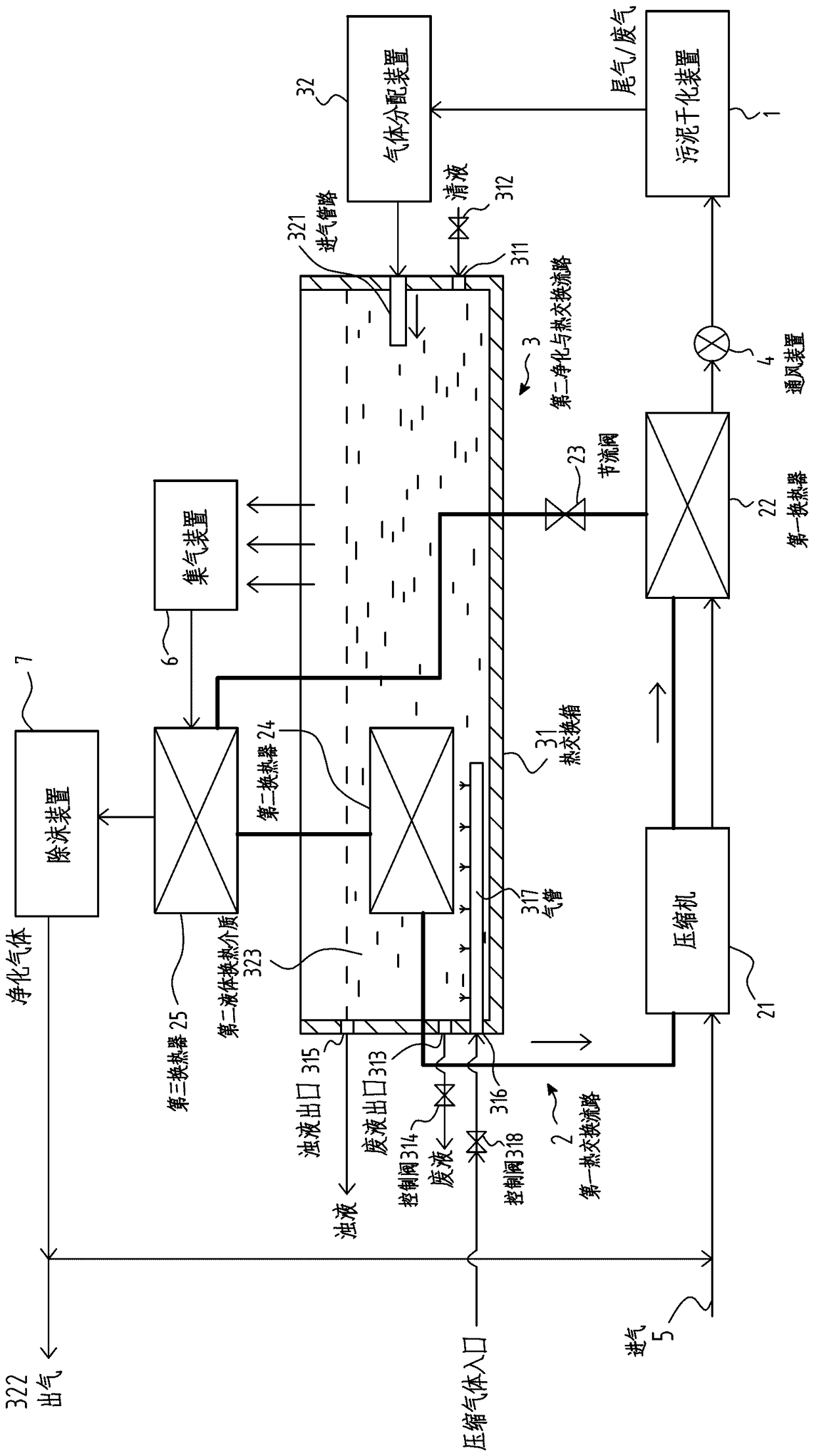
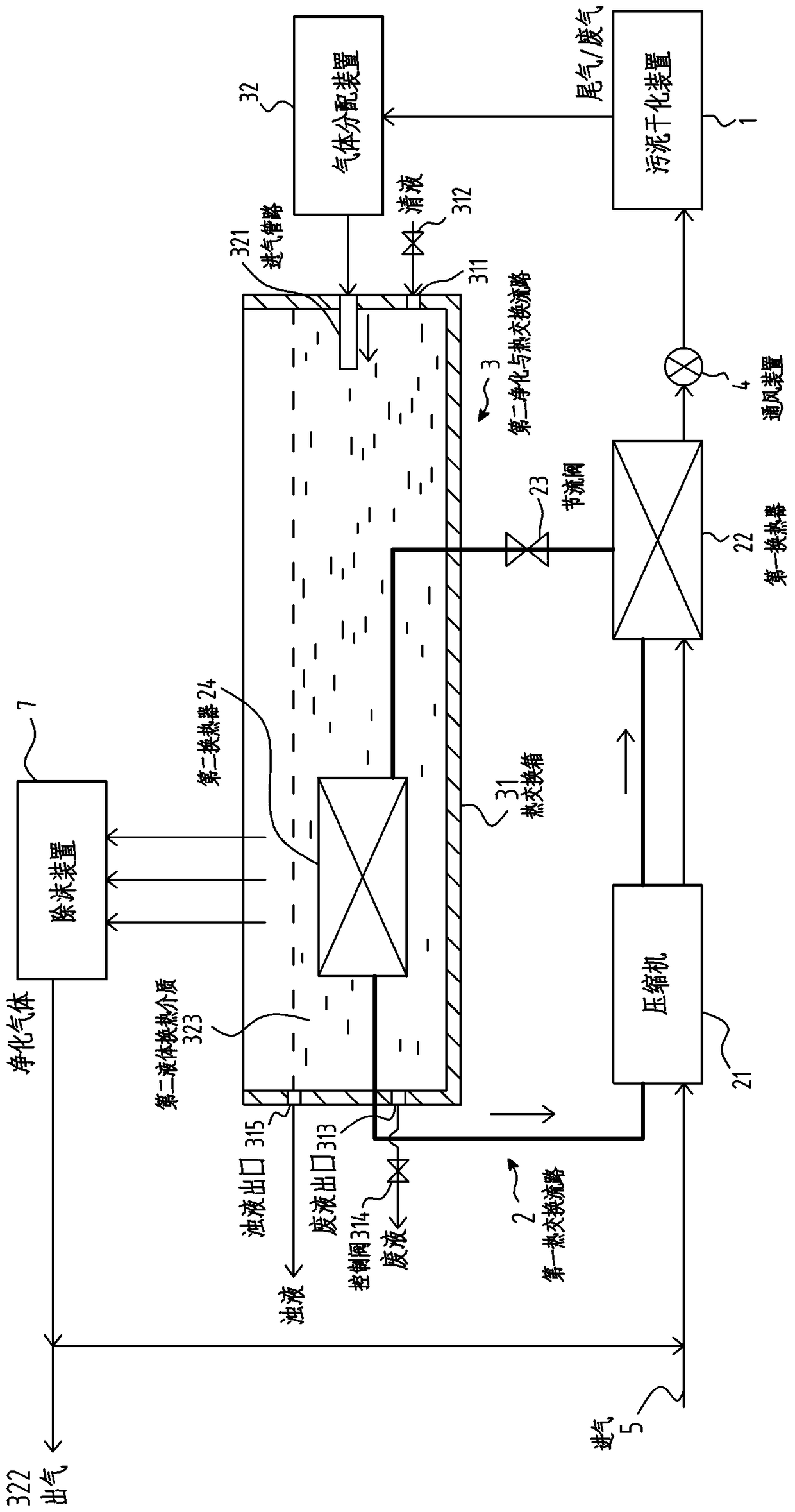
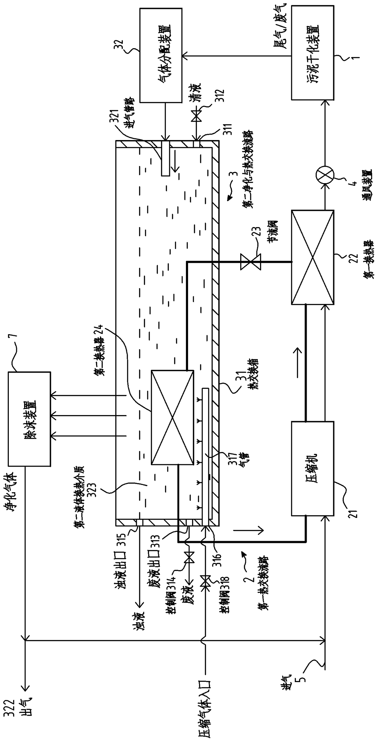
[0082] The following description is merely exemplary in nature and is in no way intended to limit the invention, its application, or uses. With reference to the accompanying drawings, figure 1 is a schematic diagram of a preferred embodiment of the exhaust gas purification and heat recovery system according to the present invention. figure 2 is a schematic diagram of another preferred embodiment of the exhaust gas purification and heat recovery system according to the present invention. image 3 It is a schematic diagram of another preferred embodiment of the exhaust gas purification and heat recovery system according to the present invention. Figure 4 It is a schematic diagram of another preferred embodiment of the exhaust gas purification and heat recovery system according to the present invention. Figure 5 It is a schematic diagram of another preferred embodiment of the exhaust gas purification and heat recovery system according to the present invention.

[0083] Such...


PUM


Abstract

The invention relates to a tail gas purification and heat recovery system and method for sludge treatment. The tail gas purification and heat recovery system comprises a first heat exchange flow pathand a second purification and heat exchange flow path and a third gas purification and recovery flow path, ; the first heat exchange flow path comprises a first heat exchanger and a second heat exchanger arranged downstream of the first heat exchanger, and a first heat exchange medium is circulated in the first heat exchange flow path so as to heat treatment gas used for sludge treatment in the first heat exchanger; and the second purification and heat exchange flow path comprises a heat exchange tank containing a second liquid heat exchange medium, the tail gas obtained after sludge treatmentis discharged into the heat exchange tank, is cleaned by a second liquid heat exchange medium in the heat exchange box and transmits heat to the second liquid heat exchange medium so as to be cooled,the second heat exchanger is in heat exchange relation with the second liquid heat exchange medium in the heat exchange box so as to transfer the heat of the second liquid heat exchange medium to thefirst heat exchange medium in the second heat exchanger. According to the third purification gas recovery flow path, through the third gas purification and recovery flow path, at least a part of thetail gas purified by the heat exchange box is guided back to the first heat exchanger through a gas inlet so as to circularly utilize the processing gas.

Description

technical field [0001] The invention relates to a tail gas purification and heat recovery system and method for sludge treatment, more particularly to a tail gas purification and heat recovery system and method for sludge treatment. Background technique [0002] With the continuous development of urbanization, the amount of sewage produced in industrial production and life that needs to be treated is gradually increasing, and as a by-product of sewage treatment-the output of sludge is also increasing. However, compared with sewage, the treatment of sludge is more difficult. At present, sludge drying treatment is a relatively effective sludge treatment method. The better drying treatment usually adopts direct drying, and the drying medium after drying is recycled and reused. [0003] Chinese invention patent CN201010101024.8 discloses a latent heat exchange type multi-phase change sludge drying method and equipment. This kind of equipment is mainly to send the dehydrated s...

Claims


Application Information

Patent Timeline
Patent Type & Authority Applications(China)
IPC IPC(8): F28D7/00F25B30/02C02F11/12B01D47/02
CPCB01D47/02F25B30/02F28D7/00C02F11/12Y02P70/10
Inventor 谭玮
Owner 广州正晟科技有限公司
Why Eureka
Try Eureka