Gas turbine heat recovery device

A technology of heat recovery device and gas turbine, which is applied in the direction of gas turbine device, steam engine device, jet propulsion device, etc., which can solve the problems of environmental pollution, heat energy loss, high exhaust gas temperature of gas turbine, etc., to avoid air pollution, reduce consumption, and increase exposure area effect

Pending Publication Date: 2018-12-18
GUANGDONG YEA ENERGY SAVING TECH
View PDF10 Cites 1 Cited by
  • Summary
  • Abstract
  • Description
  • Claims
  • Application Information

AI Technical Summary

Problems solved by technology

However, the exhaust gas temperature of the gas turbine is high. If the high-temperature flue gas is directly discharged into the atmosphere without treatment, it will not only cause heat loss, but also pollute the environment.

Method used


Image

  • Gas turbine heat recovery device
  • Gas turbine heat recovery device

Examples


Embodiment 1

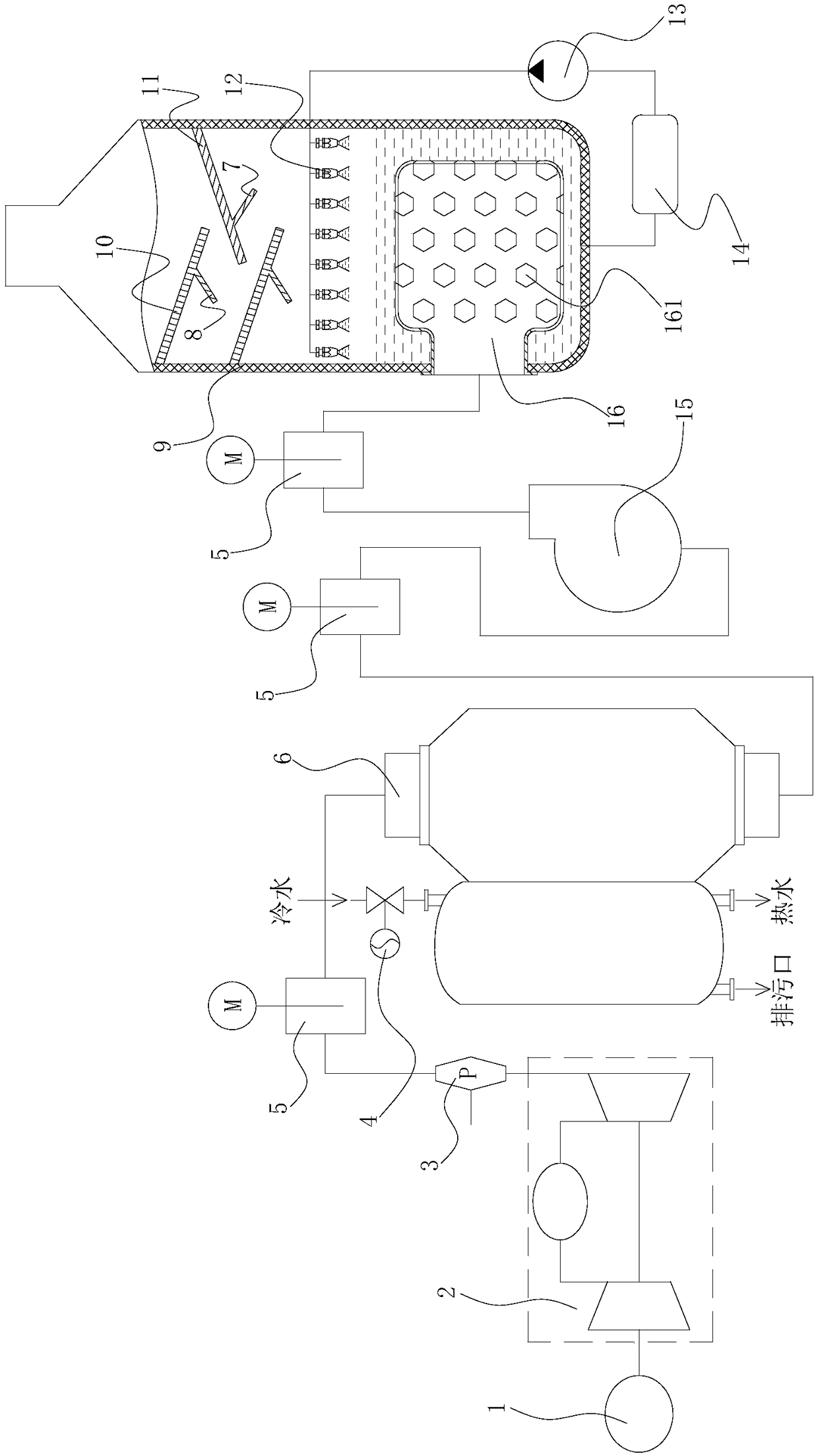
[0020] like figure 1 As shown, the present embodiment provides a gas turbine heat recovery device, including a gas turbine 2, a waste heat hot water boiler 6, a fan 15, and an exhaust discharge tower 9; the output shaft of the gas turbine 2 is connected to a working machine, such as a generator; The exhaust port is connected to the flue gas inlet of the waste heat hot water boiler 6; the flue gas outlet of the waste heat hot water boiler 6 is connected to the air inlet of the fan 15; A recovery area, a spray area, and an exhaust gas treatment area are arranged sequentially from top to bottom; a lye pool is arranged in the tail gas treatment area. 2 The exhausted tail gas is reacted to remove the acid gas in the tail gas. A gas dispersion box 16 is arranged in the lye pool; the gas dispersal box 16 is connected to the air outlet of the fan 15, and the wall of the gas dispersal box 16 is provided with a plurality of through holes communicating with the lye pool 161; through th...

Embodiment 2

[0022] like figure 1As shown, in this embodiment, on the basis of Embodiment 1, a first back hook plate 8 is fixed on the side of the first baffle plate 10 facing the second baffle plate 11; The inner wall direction of the tail gas discharge tower 9 extends; the second back hook plate 7 is fixed on the side of the second baffle plate 11 towards the first baffle plate 10; The inner wall direction of 9 extends. By setting the back hook plate, the collision time between the exhaust gas and the baffle is increased, so as to increase the amount of alkaline solution recovered and avoid the waste of alkaline solution.

Embodiment 3

[0024] Present embodiment is on the basis of embodiment 1 or 2, as figure 1 As shown, a filter device 14 is arranged between the lye pool and the circulating pump 13; the filter device 14 is located outside the tail gas discharge tower 9. Filtering device 14 is set to filter impurities such as dust in the alkaline solution to avoid clogging of circulation pump 13, and filtering device 14 is arranged outside exhaust gas discharge tower 9, which greatly facilitates the replacement of filtering device 14. In this embodiment, the filter device 14 is an activated carbon filter device.


PUM


Abstract

The invention belongs to the technical field of gas turbine heat recovery, and discloses a gas turbine heat recovery device. The gas turbine heat recovery device comprises a gas turbine, a waste heathot water boiler, a fan and an exhaust gas emission tower. A smoke exhaust outlet of the gas turbine is connected with a smoke inlet of the waste heat hot water boiler, and a smoke outlet of the wasteheat hot water boiler is connected with an air inlet of the fan. An exhaust outlet is formed in the top of the exhaust gas emission tower, and a recovery region, a spraying region and an exhaust gastreatment region are arranged in the exhaust gas emission tower in sequence from top to bottom. According to the gas turbine heat recovery device, cold water in the waste heat hot water boiler is heated by the waste heat of the exhaust gas of the gas turbine, and therefore heat recovery of the gas turbine is achieved, and the energy saving purpose is achieved. Meanwhile, due to the fact that an alkali liquor pool, a circulating pump and spraying nozzles are arranged, the purpose of removing the acidic gas in the exhaust gas is achieved, the phenomenon that the atmospheric pollution is caused by the exhaust gas is avoided, and the purpose of environmental protection is achieved.

Description

technical field [0001] The invention belongs to the technical field of gas turbine heat recovery, and in particular relates to a gas turbine heat recovery device. Background technique [0002] A gas turbine is an internal combustion power machine that uses continuous flowing gas as the working medium to drive the impeller to rotate at high speed, and converts the energy of the fuel into useful work. It is a rotary impeller heat engine. The gas turbine has a simple structure and has a series of advantages such as small size, light weight, fast start-up, and little or no cooling water. In the main process of air and gas in the gas turbine, only the gas turbine cycle composed of three major components: the compressor (Compressor), the combustor (Combustor) and the gas turbine (Turbine), is generally called a simple cycle. Most gas turbines use a simple cycle scheme. [0003] The working process of the gas turbine is that the compressor continuously sucks in air from the atmos...

Claims


Application Information

Patent Timeline
Patent Type & Authority Applications(China)
IPC IPC(8): F01K23/10F01K13/00F01K27/00F02C6/18F02C7/00
CPCF01K13/00F01K23/10F01K27/00F02C6/18F02C7/00
Inventor 张帆谭正曲泓俐莫子耘黄雪云
Owner GUANGDONG YEA ENERGY SAVING TECH
Why Eureka
Try Eureka