
Ergonomic capacitance pen

An ergonomic, capacitive pen technology, applied in the direction of electrical digital data processing, data processing input/output process, printing, etc., can solve the problems of sore hands, unsuitable for long-term use, hand burden, etc.

Inactive Publication Date: 2017-04-26
WALTOP INT
View PDF3 Cites 1 Cited by
  • Summary
  • Abstract
  • Description
  • Claims
  • Application Information

AI Technical Summary

Problems solved by technology

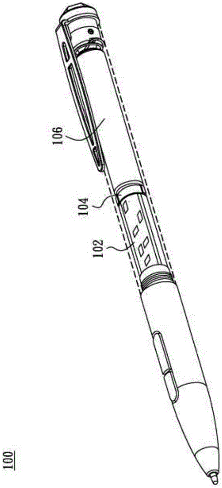
Because most people are used to incline the capacitive stylus 100 at ordinary times, when using the capacitive stylus 100 to write on the touch device, the center of gravity of the capacitive stylus 100 will fall on the upper end of the capacitive stylus 100 (due to the battery holder 104 The increased weight after installing the battery 106) will cause a burden on the hands, which will cause sore hands after long-term use
Therefore, for users (such as writers, illustrators, or other text or drawing workers) who need to use a capacitive pen for a long time to write, the traditional capacitive pen does not meet its requirements for a capacitive pen that must be comfortable and long-term use. Does not cause hand soreness requirements, not suitable for prolonged use

Method used


Image

  • Ergonomic capacitance pen
  • Ergonomic capacitance pen
  • Ergonomic capacitance pen

Examples


Embodiment Construction

[0039] Some embodiments of the invention are described in detail below. However, the invention can be broadly practiced in other embodiments than this detailed description. That is, the scope of the present invention is not limited by the presented embodiments, but by the scope of the appended claims of the present invention. Secondly, when each component or step in the diagram of the embodiment of the present invention is described as a single component or step, it should not be regarded as a limited cognition, that is, when the following description does not particularly emphasize the limitation on the number, the present invention The spirit and scope of application can be extended to structures and methods in which multiple components or structures coexist. Furthermore, in this specification, different parts of each component are not drawn in full scale, and some dimensions are exaggerated or simplified compared with other relevant dimensions, so as to provide a clearer d...


PUM


Abstract

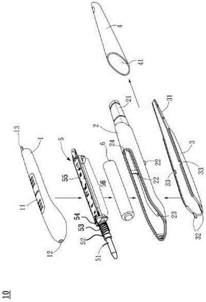
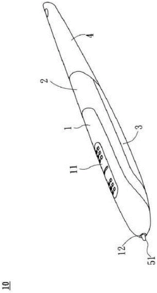
The present invention relates to an ergonomic capacitance pen. The ergonomic capacitance pen comprises an electrical signal transmitting module and a housing. The electrical signal transmitting module is deposited inside the housing. The electrical signal transmitting module comprises a core, a core holder, a spring, a sensor holder, a circuit board, and a battery holder. The battery holder is deposited on one surface of the circuit board and they are parallel with each other. When a battery is put into the battery holder, the battery and the circuit board are parallel with each other. Therefore, the gravity center of the ergonomic capacitance pen moves to the position near the head of the ergonomic capacitance pen, and the ergonomic capacitance pen can have a structure having best proportion of allocation for easily holding the ergonomic capacitance pen.

Description

technical field [0001] The invention relates to an electric digital data processing device, in particular to a capacitor pen which achieves the easiest specific gravity distribution for the human body to hold the pen by changing the placement position of the battery. Background technique [0002] With the popularization of touch devices, capacitive pens are also widely used in various touch devices (such as touch panels, touch mobile phones, tablet computers, etc.) for handwriting input. see figure 1 As shown, it is a schematic diagram of a general traditional capacitive pen 100 (the second half of the capacitive pen 100 is a perspective view), and the traditional capacitive pen 100 usually has a battery holder 104 arranged behind the circuit board 102 (that is, the capacitive pen 100 end), so that the center of gravity of the capacitive stylus 100 will fall on the tail end of the capacitive stylus 100 (ie, the upper end of the capacitive stylus 100). Because most people a...

Claims


Application Information

Patent Timeline
Patent Type & Authority Applications(China)
IPC IPC(8): G06F3/0354
CPCG06F3/03545G06F3/0383G06F3/0442B43K24/00
Inventor 茆中甫何行江
Owner WALTOP INT
Learn More