Voltage dislocation circuit, driving method thereof, driving device and display device

A technology for display equipment and driving methods, applied in the direction of output power conversion devices, electrical components, and adjusting electrical variables, etc., can solve problems such as flickering screens, achieve the effects of avoiding flickering screens, realizing high-low level conversion, and saving power consumption

Active Publication Date: 2019-11-05
BOE TECH GRP CO LTD +1
View PDF8 Cites 0 Cited by
  • Summary
  • Abstract
  • Description
  • Claims
  • Application Information

AI Technical Summary

Problems solved by technology

However, the above method will have a flickering problem at high temperature reliability

Method used


Image

  • Voltage dislocation circuit, driving method thereof, driving device and display device
  • Voltage dislocation circuit, driving method thereof, driving device and display device
  • Voltage dislocation circuit, driving method thereof, driving device and display device

Examples


Embodiment 1

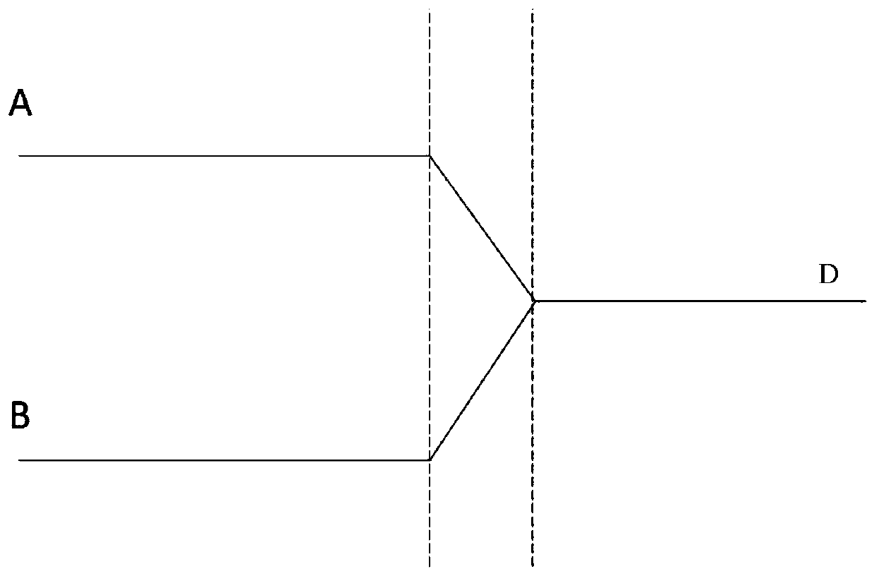
[0029] figure 1 It is a schematic diagram of switching between high and low levels in the prior art. Such as figure 1 As shown, the prior art raises and lowers the high and low voltages to the same reference voltage at the same time through charge sharing. The conversion times of the two completely coincide. Therefore, the above method will have a flickering problem when it is reliable at high temperature. In order to solve the above problems, the present invention provides a voltage dislocation circuit, which is specifically described as follows:

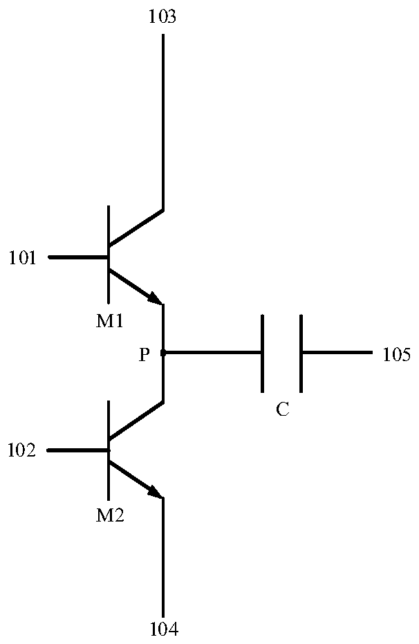
[0030] figure 2 It is a schematic structural diagram of a voltage dislocation circuit provided by Embodiment 1 of the present invention. Such as figure 2 As shown, the voltage dislocation circuit includes the following ports: a first input terminal 101, a second input terminal 102, a first voltage terminal 103, a second voltage terminal 104 and an output terminal 105, and the first input terminal 101 is used for inputting ...

Embodiment 2

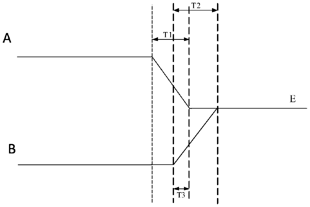
[0036] This embodiment provides a method for driving a voltage dislocation circuit. The voltage dislocation circuit includes the following ports: a first input terminal, a second input terminal, a first voltage terminal, a second voltage terminal, and an output terminal. The first input terminal The terminal is used to input the first signal, the second input terminal is used to input the second signal, the first voltage terminal is used to input the first voltage, the second voltage terminal is used to input the second voltage, and the output The terminal is used to output the output signal. The driving method of the voltage dislocation circuit includes: the voltage dislocation circuit reduces the first voltage to the output voltage within a first time, and increases the second voltage to the output voltage within a second time. the output voltage, the first time partly coincides with the second time.

[0037] Figure 4 A working sequence diagram of a voltage dislocation ci...

Embodiment 3

[0043] This embodiment provides a driving device, including the voltage dislocation circuit provided in Embodiment 1. For details, please refer to the description of Embodiment 1, which will not be repeated here.

[0044] In the driving device provided in this embodiment, the voltage dislocation circuit includes the following ports: a first input terminal, a second input terminal, a first voltage terminal, a second voltage terminal and an output terminal, and the first input terminal is used to input the second A signal, the second input terminal is used to input a second signal, the first voltage terminal is used to input a first voltage, the second voltage terminal is used to input a second voltage, and the output terminal is used to output signal; the voltage shift circuit is used to reduce the first voltage to the output voltage within a first time, and increase the second voltage to the output voltage within a second time, the The first time partially coincides with the s...


PUM


Abstract

The present application discloses a voltage shift circuit and a driving method thereof, a driving device and a display apparatus. The voltage shift circuit includes: a first input terminal, a second input terminal, a first voltage terminal, a second voltage terminal, and an output terminal. The first input terminal is configured to input a first signal. The second input terminal is configured to input a second signal. The first voltage terminal is configured to input a first voltage. The second voltage terminal is configured to input a second voltage. The output terminal is configured to output an output signal. The voltage shift circuit is configured to lower the first voltage to an output voltage within a first time using the first signal, and to raise the second voltage to the output voltage within a second time using the second signal. The first time partially overlaps with the second time.

Description

technical field [0001] The invention relates to the field of display technology, in particular to a voltage dislocation circuit, a driving method thereof, a driving device and a display device. Background technique [0002] The existing driving technology charges and discharges the load during the transition process of the high and low levels of the two clock signals, thereby increasing the power consumption. In order to save power consumption, in the prior art, the high and low voltages are simultaneously raised and lowered to the same reference voltage by way of charge sharing. However, the above method will have a flickering problem at high temperature reliability. Contents of the invention [0003] In order to solve the above problems, the present invention provides a voltage dislocation circuit and its driving method, driving device and display device, at least partially solving the problem of flickering in the prior art at high temperature reliability. [0004] To ...

Claims


Application Information

Patent Timeline
Patent Type & Authority Patents(China)
IPC IPC(8): G09G3/20H02M3/158
CPCG09G3/20H02M3/158G09G2310/0289G09G2330/021G09G2310/08
Inventor 高贤永侯帅肖利军徐波伏思庆陆旭余强梁利生陈帅尚飞
Owner BOE TECH GRP CO LTD
Why Eureka
Try Eureka