Robot joint zero point automatic calibration end effector and method thereof

A robot joint, automatic calibration technology, applied in the direction of measuring devices, optical devices, instruments, etc., can solve the problems of difficult to guarantee reliability, low efficiency, unsatisfactory and other problems, to reduce processing accuracy and cost, save labor, improve The effect of controlling precision

Active Publication Date: 2019-09-17
COMAU KUNSHAN AUTOMATION
View PDF8 Cites 0 Cited by
  • Summary
  • Abstract
  • Description
  • Claims
  • Application Information

AI Technical Summary

Problems solved by technology

Since the data is recorded by human eyes, it will inevitably cause mistakes, it is difficult to guarantee absolute reliability, and the efficiency is low
Even with a sensor-type micrometer, although it can automatically record the lowest point of the V-groove, it still needs to be manually installed and uninstalled for each joint axis many times, which is still not satisfactory.

Method used


Image

  • Robot joint zero point automatic calibration end effector and method thereof
  • Robot joint zero point automatic calibration end effector and method thereof
  • Robot joint zero point automatic calibration end effector and method thereof

Examples


Embodiment Construction

[0017] In order to deepen the understanding of the present invention, the present invention will be further described below in conjunction with the embodiments and accompanying drawings. The embodiments are only used to explain the present invention and do not constitute a limitation to the protection scope of the present invention.

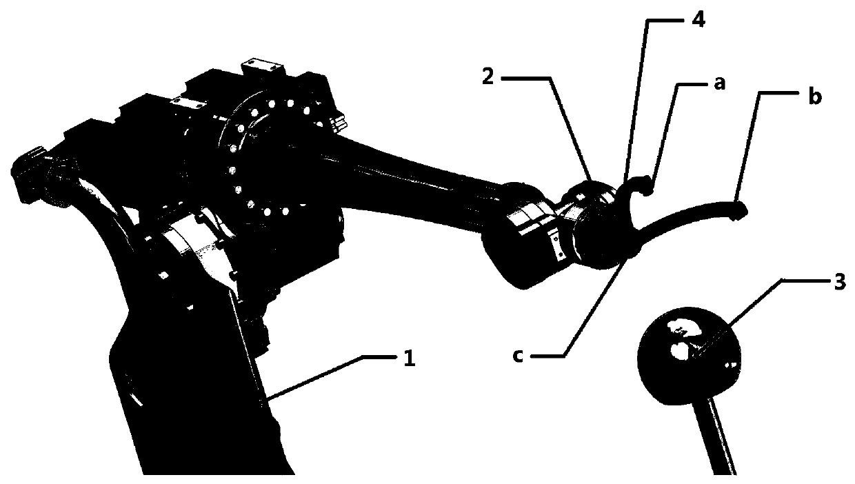
[0018] figure 2 It shows an embodiment of a robot joint zero point automatic calibration end effector of the present invention, which includes a mechanical gripper 2 installed on the robot body 1 and an external positioning ball 3. The mechanical gripper 2 consists of three The mutually orthogonal and vertical laser distance sensors 4 are composed of laser distance sensors a, laser distance sensors b and laser distance sensors c respectively. The three laser distance sensors 4 are located on the surface of the positioning ball 3 by contact.

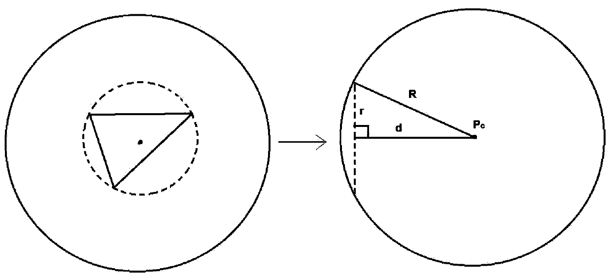
[0019] Such as Figure 4 The shown automatic calibration method for the robot joint zero point for cali...


PUM


Abstract

The invention discloses a robot joint zero-point automatic calibration end performing device, and the device comprises a mechanical arm disposed on a robot body, and an external positioning ball. The mechanical arm consists of three laser distance sensors which are perpendicular to each other. The three laser distance sensors are used for carrying out the automatic calibration of a robot joint through touching the surface of the positioning ball. The device is high in precision, is lossless, and is stable in long-time performance. An automatic calibration method is used for directly measuring the position and vector of each shaft, thereby avoiding the calculation and model errors, improving the control precision of a robot, and reducing the machining precision and cost of the robot.

Description

technical field [0001] The invention relates to the technical field of robot automation, in particular to an end effector and a method thereof for automatically calibrating the zero point of a robot joint. Background technique [0002] At present, all robot brands need to calibrate each joint of the robot after the robot is assembled and before it leaves the factory. However, the traditional calibration method is cumbersome and inefficient. The traditional method is to perform zero point calibration for each joint axis one by one with a micrometer. Such as figure 1 As shown, when the thimble touches the lowest point of the V-shaped groove, record the data and mark it as zero point, and the V-shaped groove is located on the circumference of the robot joint. Because the data is recorded by human eyes, it will inevitably cause mistakes, it is difficult to guarantee absolute reliability, and the efficiency is low. Even if a sensor-type micrometer is used, although it can auto...

Claims


Application Information

Patent Timeline
Patent Type & Authority Patents(China)
IPC IPC(8): G01B11/00
Inventor 陶宗杰
Owner COMAU KUNSHAN AUTOMATION
Why Eureka
Try Eureka