Optical fiber monitoring and checking system

A technology of optical fiber and judgment module

Inactive Publication Date: 2017-05-03
SINOLASER PROJECTION TECH
View PDF5 Cites 8 Cited by
  • Summary
  • Abstract
  • Description
  • Claims
  • Application Information

AI Technical Summary

Problems solved by technology

[0006] Up to now, there is no system specially applied to laser fiber monitoring and detection on the market

Method used


Image

  • Optical fiber monitoring and checking system
  • Optical fiber monitoring and checking system
  • Optical fiber monitoring and checking system

Examples


Embodiment 1

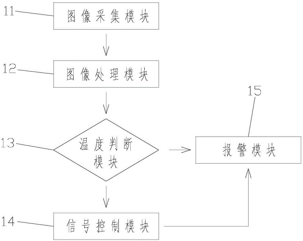
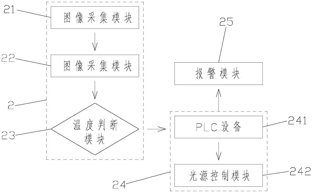
[0039] Embodiment 1: as attached figure 2 The shown optical fiber monitoring and breaking system includes: image acquisition module 21: used to collect image information within the monitoring range; image processing module 22: used to convert the collected image information into temperature distribution information; temperature judgment module 23: It is used to judge whether there is an abnormal temperature point exceeding the set value in the temperature distribution information; the signal control module 24: judges the alarm signal for transmitting the abnormal temperature point, and controls the switch state of the light source; the alarm module 25: judges the module or the signal control module according to the temperature The abnormal temperature information fed back will be sent to the police. When the temperature judging module 23 sends temperature abnormal point information to the signal control module 24 ; the temperature judging module 23 is disconnected from the al...

Embodiment 2

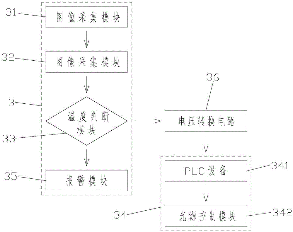
[0043] Embodiment 2: as attached image 3 The shown optical fiber monitoring and detection system includes: image acquisition module 31: used to collect image information within the monitoring range; image processing module 32: used to convert the collected image information into temperature distribution information; temperature judgment module 33: It is used to judge whether there is an abnormal temperature point exceeding the set value in the temperature distribution information; the signal control module 34: judges the alarm signal for transmitting the abnormal temperature point, and controls the switch state of the light source; the alarm module 35: judges the module or the signal control module according to the temperature The abnormal temperature information fed back will be sent to the police. When the temperature judging module 33 sends temperature abnormal point information to the alarm module 34 and the signal control module 35 , the signal control module 34 is disco...


PUM


Abstract

The invention discloses an optical fiber monitoring and checking system, which belongs to the technical field of laser application. The system comprises an image acquisition module which is used for collecting image information in a monitoring range, an image processing module which is used for converting the collected image information into temperature distribution information, a temperature judgment module which is used for judging whether a temperature abnormity point which exceeds a set value is in temperature distribution information, a signal control module which judges an alarm signal which transmits the temperature abnormity point to control the switch state of a light source, and an alarm module which gives an alarm according to abnormal temperature information fed back by the temperature judgment module or the signal control module. The image acquisition module, the image processing module, the temperature judgment module, the signal control module and the alarm module are connected in turn. The temperature judgment module is connected with the alarm module. The optical fiber monitoring and checking system provided by the invention improves the safety of a running optical fiber, and is of great significance to ensure the quality and running stability of a laser display product.

Description

technical field [0001] The invention relates to an optical fiber monitoring and detection system, in particular to a system for monitoring whether a laser optical fiber is broken during operation, and capable of realizing an alarm and signal control to turn off a light source, belonging to the technical field of laser applications. Background technique [0002] Because of its strong monochromaticity, coherence and directionality, laser is widely used in the fields of electronics, automobile manufacturing, and medical treatment. [0003] In recent years, with the continuous development and progress of laser light source technology, laser display has been continuously introduced to the market as a new display technology, and has become the leader of high-end display with its advantages of high brightness, wide color gamut and long life. [0004] In laser display products, especially in high-brightness engineering machine products, optical fibers are channels for transmitting l...

Claims


Application Information

Patent Timeline
Patent Type & Authority Applications(China)
IPC IPC(8): G01J5/00G01M11/08
CPCG01J5/0066G01J5/0096G01M11/088
Inventor 聂思永赵振宇许心兵刘晋欧伟
Owner SINOLASER PROJECTION TECH
Why Eureka
Try Eureka