
An all-round locking assembly machine for gear shaft parts

一种全方位、装配机的技术,应用在组装机、工件夹持装置、金属加工设备等方向,能够解决齿轴损害程度高、影响组装效果、安装质量不统一等问题,达到提高适应范围、良好压入效果、提高效果的效果

Active Publication Date: 2018-09-25
XUZHOU WANXU MASCH CO LTD
View PDF5 Cites 0 Cited by
  • Summary
  • Abstract
  • Description
  • Claims
  • Application Information

AI Technical Summary

Problems solved by technology

[0003] The gear shaft installation in the machinery industry is usually done by manual hammering or manual press installation; the quality of the gear shaft installed by hammering is more accidental, the installation quality is not uniform, and due to the force The force on the point is uneven. When the gear shaft is installed, it does not go in smoothly but obliquely, resulting in a high degree of damage to the gear shaft, especially to the inner ring of the gear shaft. The mechanical service life and reliability of the pinion shaft are adversely affected; because the fixed block in the middle of the pinion shaft is of irregular shape, it is difficult to fix the pinion shaft during the installation process, and most of the existing pinion shaft presses can only The gear shaft is sleeved on the carrier, and the middle fixed block is not used for positioning. This requires a large clamping force to ensure that the gear shaft does not deflect when installing the gear and the short shaft. However, excessive pressure is easy to damage the gear shaft. Therefore, it is difficult to ensure that the gear shaft does not deviate during the machining process, which will affect the assembly effect

Method used


Image

  • An all-round locking assembly machine for gear shaft parts
  • An all-round locking assembly machine for gear shaft parts
  • An all-round locking assembly machine for gear shaft parts

Examples


Embodiment Construction

[0033] In order to enable those skilled in the art to better understand the technical solution of the present invention, the present invention will be described in detail below in conjunction with the accompanying drawings. The description in this part is only exemplary and explanatory, and should not have any limiting effect on the protection scope of the present invention. .

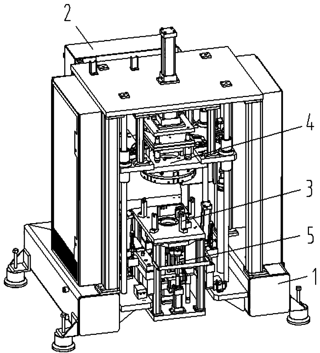
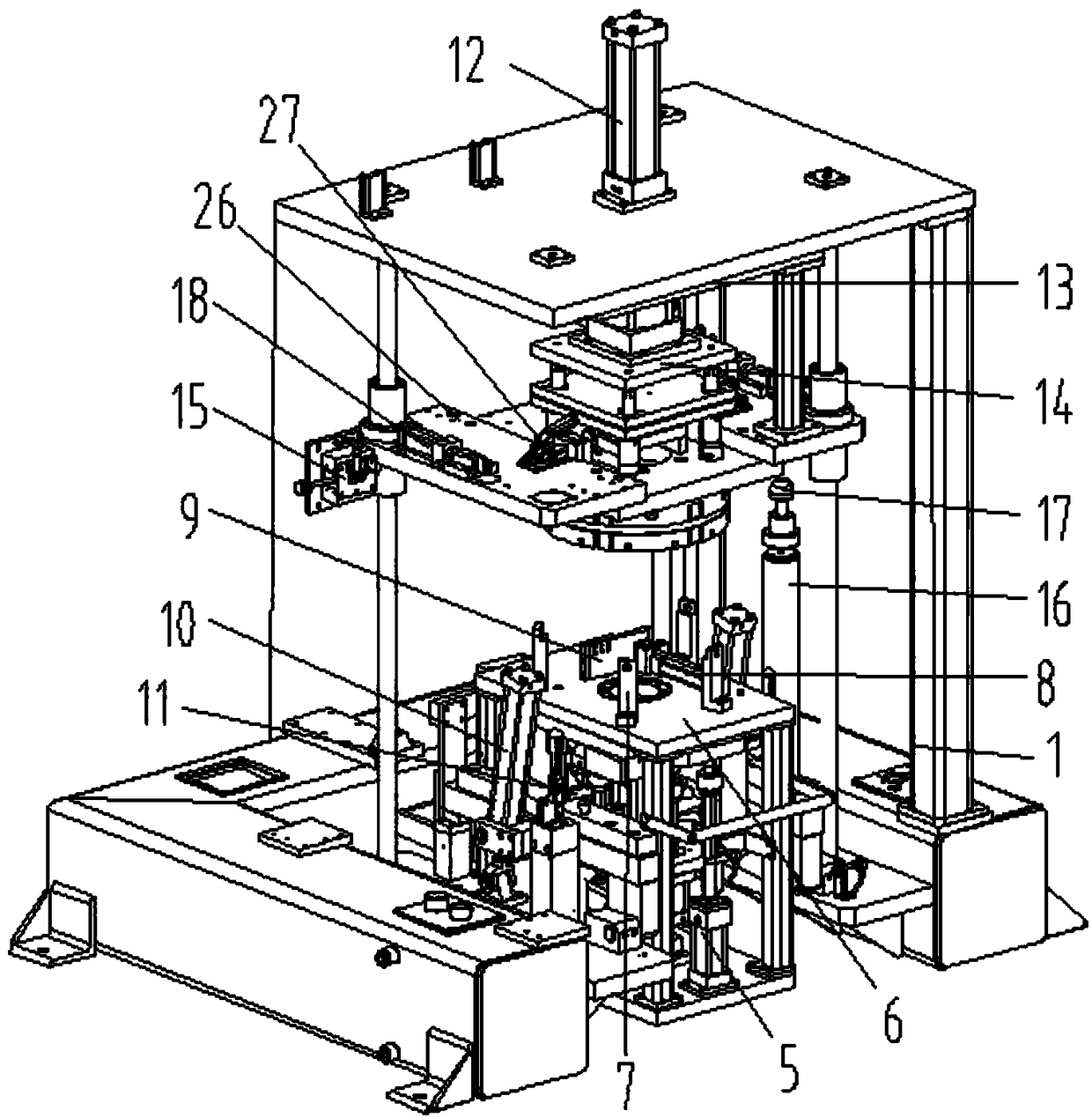
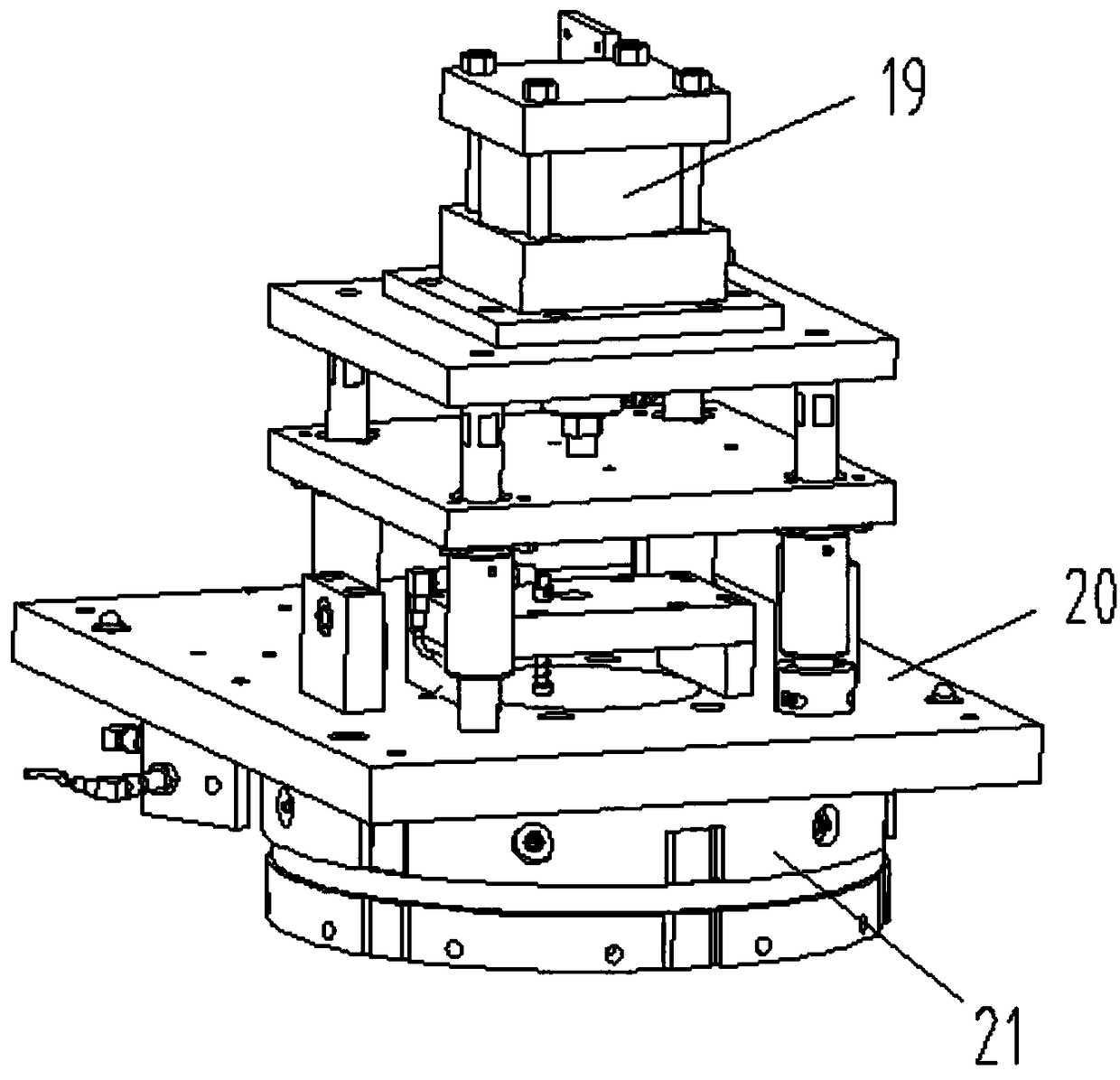
[0034] Such as Figure 1-Figure 8As shown, the specific structure of the present invention is: an all-round locking assembly machine for gear shaft parts, which includes a frame 1 and a power distribution control box 2, and the frame 1 is provided with a lock that cooperates with the gear shaft 36. Tighten the carrier device 3, the upper part of the locking carrier device 3 is equipped with a gear sleeve mechanism 4, and the lower part is equipped with a short shaft insertion device 5, and the frame 1 is provided with a center opening with a diameter larger than the diameter of the gear shaft The carr...


PUM


Abstract

The invention relates to a gear shaft part comprehensive locking assembler. The gear shaft part comprehensive locking assembler comprises a frame and a power distribution control box; the frame is provided with a locking carrier device matched with a gear shaft; the locking carrier device is matched with a gear sleeving mechanism on the upper side and a short shaft inserting device on the lower side; the frame is provided with a carrier base; a hole with the aperture larger than the diameter of the gear shaft is formed in the center of the carrier base; the carrier base is provided with a fixed clamping block and a movable clamping block matched with each other; the movable clamping block is connected with a movable clamping cylinder on the carrier base; the fixed clamping block and the movable clamping block are matched with a middle fixed block on the gear shaft; and the gear sleeving mechanism, the short shaft pressing mechanism and the movable clamping cylinder are connected to the power distribution control box. The gear shaft part comprehensive locking assembler comprehensively clamps the irregular middle fixed block through the fixed clamping block and the movable clamping block, guarantees no deviation of the gear shaft in the assembly process, and meanwhile, prevents a fixed part from directly acting on the gear shaft to prevent damage of the gear shaft so as to improve the assembly effect.

Description

technical field [0001] The invention relates to the field of gear shaft processing equipment, in particular to an omnidirectional locking assembly machine for gear shaft parts. Background technique [0002] The application of gear shaft parts is very extensive, and it is used in all walks of life. Most of them are as Figure 7 and Figure 8 As shown, it includes the fixedly connected pinion shaft 36 and the middle fixed block 37. The upper part of the pinion shaft needs to be inserted into the gear 38, and the lower part of the pinion shaft needs to be inserted into the short shaft with steps, and most of the steps are sequentially reduced from top to bottom. Little, there are the middle part fixed block 37 of some pinion parts to be fixedly connected with cover plate 40, and the two ends of cover plate have matching hole. [0003] The gear shaft installation in the mechanical industry is usually done by manual hammering or manual press installation; the quality of the gear...

Claims


Application Information

Patent Timeline
Patent Type & Authority Patents(China)
IPC IPC(8): B23P21/00
CPCB23P19/027B23P21/002B25B11/02
Inventor 邓君徐红娇何楚亮
Owner XUZHOU WANXU MASCH CO LTD
Learn More