
Shaft pulling device used for pulling airplane anti-icing valve guide shaft and shaft pulling method
A technology for guide shafts and shaft pullers, which is applied in the field of shaft pullers and shaft puller tools. It can solve the problems of difficult disassembly, difficult disassembly, and easy jamming of housing components and guide shaft components, and achieves convenient processing and easy operation. , its own solid effect
- Summary
- Abstract
- Description
- Claims
- Application Information
AI Technical Summary
Problems solved by technology
Method used
Image

Examples
Embodiment Construction
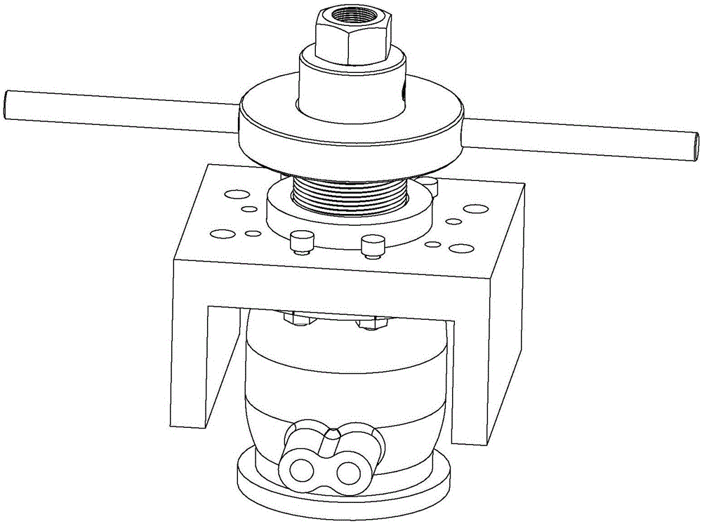
[0061] Such as figure 1 Shown is the perspective view of the embodiment of the aircraft anti-icing valve guide shaft puller of the present invention, and the embodiment includes the following parts:
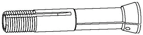
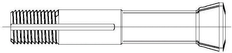
[0062] A tubular taper pipe thread sleeve 3, diameter is 21mm, and overall length is 101.5mm, and one end is shaped on the external thread of 71.5mm height (thread and the rotating nut 4 internal threads of the back cooperate), and the other end is drilled with transverse thread through hole so that The wrench handle 5 cooperates, the distance between the center of the through hole and the uppermost edge of the tapered tube screw sleeve 3 is 14mm, the inner hole at the end of the external thread is a bell mouth, the diameter of the conical bottom surface is 31.28mm, the diameter of the upper surface is 21mm, and the taper is 30 °, the internal design dimension of tapered tube threaded sleeve 3 is to allow it to match with lock mouth 1. see Figure 4-1 to Figure 4-3 .
[0063] ...
PUM
 Abstract
Description
Claims
Application Information